GE IC660BRD024C1 Retrofit-Ready Redundancy T Output Module: Compatible Upgrade for Genius I/O Control Systems
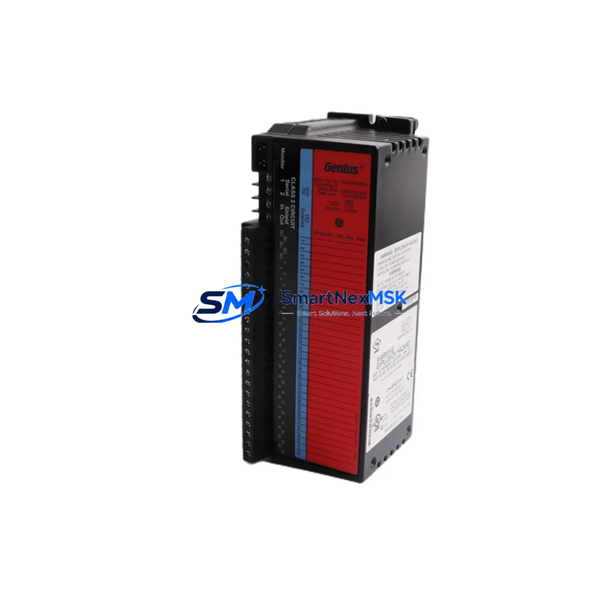
The GE IC660BRD024C1 is a Redundancy T Output Module designed for GE Fanuc Genius I/O distributed I/O systems — one of the most widely deployed fieldbus architectures in process automation, discrete manufacturing, and utility control environments. As GE Fanuc’s Genius I/O platform approaches end-of-life support milestones, plant engineers and system integrators are increasingly sourcing verified replacement units to sustain aging control infrastructure without committing to a full platform migration. The IC660BRD024C1 remains a critical component in redundant output configurations where uninterrupted field device control is non-negotiable.
This module operates on the Genius Bus — a single-cable, token-passing fieldbus that connects distributed I/O blocks directly to a Series 90-70 or Series 90-30 PLC host controller. In redundant configurations, the IC660BRD024C1 works in tandem with a primary output block, taking over field output control seamlessly in the event of a primary module fault. Replacing a failed or degraded IC660BRD024C1 requires careful attention to bus address configuration, terminal wiring continuity, and redundancy handshake parameters stored in the host PLC program — typically managed through Logicmaster 90 or Proficy Machine Edition software.
Upgrade Compatibility Table
| Parameter | IC660BRD024C1 Specification | Retrofit / Upgrade Notes |
|---|---|---|
| Module Type | Redundancy T Output Block | Direct replacement for IC660BRD024 variants; verify suffix compatibility |
| Bus Interface | Genius Bus (single-cable fieldbus) | Compatible with IC660CBL500 and IC660CBL501 bus cables |
| Host Controller Compatibility | Series 90-70, Series 90-30 | Verify Genius Bus Controller (IC660BBA020 / IC660BBA100) firmware revision |
| Bus Address | Configurable via rotary switch (0–31) | Must match address stored in PLC I/O configuration table before hot-swap |
| Terminal Wiring | Field-side terminal block, 24-point output | Retain original wiring diagram; verify terminal torque spec before re-termination |
| Power Supply Requirement | 24 VDC field power (external) | Confirm IC660PWR024 or equivalent power supply capacity before installation |
| Communication Protocol | Genius Bus (proprietary GE fieldbus) | Not directly interchangeable with Profibus or DeviceNet without gateway |
| Redundancy Handshake | Hardware-based, automatic failover | Verify redundancy pair address offset in PLC program logic |
| Installation Format | DIN rail or panel mount | Mounting footprint identical to IC660BRD024 series predecessors |
| Warranty | 12-Month Warranty | Covered from date of shipment; includes functional test certification |
Retrofit Planning for Existing Automation Systems
Integrating the IC660BRD024C1 into an existing Genius I/O network requires a structured pre-installation audit. Begin by documenting the current bus topology — the number of active bus devices, their assigned addresses, and the total bus cable length. The Genius Bus supports up to 32 devices per segment, and adding or replacing a module without verifying address conflicts can cause bus communication faults that affect all downstream I/O blocks simultaneously.
Before removing the failed module, capture the current I/O configuration from the host PLC using Proficy Machine Edition or Logicmaster 90. Export the hardware configuration file and confirm the slot assignment, I/O map offsets, and any special function blocks associated with the redundancy pair. The IC660BRD024C1’s redundancy partner — typically another IC660BRD024-series block — must remain powered and communicating during the swap to maintain field output continuity.
Terminal wiring on the IC660BRD024C1 uses a removable field wiring terminal block. Before disconnecting, photograph or transcribe all field wiring connections, noting wire color, terminal number, and signal function. Cross-reference against the original panel wiring diagram. If the control cabinet also houses an IC660PWR024 field power supply or an IC660BBA020 Genius Bus Controller, verify that neither unit shows fault indicators before proceeding — a degraded bus controller can cause a replacement output module to fail bus enumeration even when the module itself is fully functional.
For systems undergoing broader modernization — such as migrating from a Series 90-70 backplane to a PACSystems RX7i or RX3i platform — the IC660BRD024C1 can continue to serve as a field I/O node via a Genius Bus Interface Unit (GBIU), preserving existing field wiring while the host controller is upgraded. This approach is particularly effective in phased retrofit projects where replacing all field I/O simultaneously is not operationally feasible. In such configurations, the IC660CBL500 bus cable, IC660BBA100 bus controller, and existing IC660 series I/O blocks can remain in service while the PLC backplane, CPU module, and power supply are replaced in a planned maintenance window.
For applications requiring I/O expansion beyond the current Genius Bus segment, consider adding an IC660BBA020 Bus Controller to a secondary segment, or evaluating VersaMax I/O modules as a parallel I/O subsystem connected via Ethernet or Profibus to the upgraded host controller. HMI screens configured in iFIX or Cimplicity that reference Genius I/O block addresses will require tag remapping if bus addresses change during the retrofit — plan HMI screen validation as a discrete commissioning step.
Downtime Control During System Migration
Minimizing unplanned downtime during an IC660BRD024C1 replacement begins with pre-staging the replacement unit and verifying its bus address switch setting before the maintenance window opens. Set the rotary address switch to match the failed module’s documented address while the replacement unit is still on the bench. Perform a visual inspection of the terminal block and bus connector for physical damage or corrosion.
During the swap, the redundancy architecture of the IC660BRD024C1 pair allows the surviving module to maintain field output states while the failed unit is removed. This eliminates the need to place the process in a safe hold state in most applications — confirm this with your process safety review before proceeding. Once the replacement module is seated and the bus cable is reconnected, the Genius Bus Controller will automatically enumerate the new module and restore redundancy status within seconds.
After installation, verify module status LEDs: the OK LED should illuminate solid green, and the Bus Active LED should flash at the bus scan rate. From the PLC programming terminal, perform an online I/O force test on a non-critical output point to confirm field wiring continuity before returning the system to automatic control. Document the replacement in the plant maintenance log, including the module serial number, installation date, and technician sign-off — this record supports the 12-month warranty claim process if a warranty event occurs.
For systems where the Genius Bus Controller itself (IC660BBA020 or IC660BBA100) is also approaching end-of-life, plan its replacement in a separate maintenance window to avoid compounding risk. Similarly, if the Series 90-70 CPU module (such as an IC697CPU772 or IC697CPU781) or its associated IC697PWR711 power supply shows degraded performance indicators, address these components in the retrofit plan before they cause unplanned outages.
Retrofit Support FAQ
Q: Is the IC660BRD024C1 a direct drop-in replacement for earlier IC660BRD024 variants?
A: In most cases, yes. The C1 suffix denotes a revision level; the module is electrically and mechanically compatible with earlier IC660BRD024 variants in standard Genius I/O redundant output applications. Verify the bus address switch setting and terminal wiring map before installation. If your system uses a customized I/O configuration block in the PLC hardware table, confirm that the module type entry matches the C1 revision to avoid configuration mismatch faults.
Q: What commissioning steps are required after installing the replacement module?
A: After physical installation, confirm the bus address switch matches the PLC hardware configuration. Power up the module and observe the OK and Bus Active LEDs. From the PLC terminal, go online and verify that the I/O block appears in the hardware configuration with no fault status. Perform an output force test on at least one field point to confirm wiring continuity. Verify redundancy status by checking that both the primary and redundancy T output blocks show healthy status in the Genius Bus diagnostic display.
Q: Can the IC660BRD024C1 be used in a system being migrated to PACSystems RX7i or RX3i?
A: Yes. The IC660BRD024C1 can continue to operate as a Genius Bus field I/O node when connected to a PACSystems host via a Genius Bus Interface Unit (GBIU). This allows phased migration where field wiring and I/O blocks are retained while the host controller platform is upgraded. Confirm GBIU firmware compatibility with your PACSystems CPU revision before commissioning.
Q: What does the 12-month warranty cover, and how is it claimed?
A: The 12-month warranty covers manufacturing defects and functional failures under normal operating conditions, effective from the date of shipment. Each unit undergoes functional testing prior to dispatch. To initiate a warranty claim, contact sales@smartnexmsk.com with your order reference, module serial number, and a description of the fault symptom. Warranty units are processed with priority handling to minimize your system downtime.
© 2026 SMARTNEXMSK. All rights reserved.
Original Source: https://smartnexmsk.com
Contact: sales@smartnexmsk.com | +86 18259474341