Generic 80190-100-01-R Retrofit-Ready PLC Control Board: Compatible Modernization & Legacy System Smooth Upgrade
The 80190-100-01-R is a retrofit-ready PLC control board engineered to serve as a direct OEM-compatible replacement for aging and discontinued control system components. Designed for industrial environments where legacy infrastructure must be preserved while operational reliability is restored, this board addresses the critical gap between end-of-life hardware and the demand for continuous production uptime. Whether you are managing a brownfield retrofit, upgrading a control cabinet, or recovering a system after a critical board failure, the 80190-100-01-R delivers the compatibility, durability, and verified performance that industrial maintenance engineers require.
Industrial automation systems built around legacy PLC platforms often face a common challenge: the original control boards become obsolete, spare parts dry up, and OEM support is discontinued. The 80190-100-01-R is purpose-built to address this scenario. It is manufactured to match the original electrical specifications, terminal layout, and backplane interface of the target control system, allowing engineers to execute a board-level swap without redesigning the control cabinet or rewriting the application program from scratch.
Before proceeding with any retrofit installation, engineers should verify several key parameters. First, confirm the power supply capacity of the existing rack or chassis — the replacement board must operate within the same voltage and current envelope as the original, typically 24 VDC or 5 VDC backplane power depending on the platform. Second, review the terminal wiring diagram against the original I/O assignment sheet to ensure field wiring can be reconnected without modification. Third, confirm the backplane slot address and module addressing scheme, as some legacy systems use DIP switch or rotary dial addressing that must be replicated on the replacement board. Fourth, verify program compatibility: if the original system was programmed using a legacy programming cable such as a dedicated RS-232 or USB-to-serial adapter, ensure the same cable and software version are available for post-installation verification and any necessary program re-download.
In systems where the 80190-100-01-R replaces a board within a multi-rack configuration, engineers should also account for the communication link between the local rack and any remote I/O racks. Protocols such as DH+ or Remote I/O (RIO) used in older Allen-Bradley SLC 500 or PLC-5 platforms, or PROFIBUS DP used in Siemens S5 and early S7 systems, must remain intact. If the retrofit involves migrating from an older communication protocol to a modern Ethernet-based network such as EtherNet/IP or PROFINET, additional communication modules and network configuration steps will be required.
HMI screen compatibility is another consideration during retrofit planning. If the existing operator interface was configured to communicate with the original board using a specific driver or node address, the replacement board must be configured to match those parameters exactly, or the HMI project must be updated accordingly. This is particularly relevant in systems using legacy PanelView terminals, Siemens OP/TP panels, or third-party SCADA software connected via serial or DDE links.
The 80190-100-01-R is suitable for use in control cabinets alongside a range of complementary components commonly found in legacy and transitional automation systems. Engineers performing a full system audit will often find that the control board replacement is accompanied by the need to inspect or replace the power supply module feeding the CPU rack, terminal block assemblies on the I/O modules, and the rack or chassis itself if physical damage or corrosion is present. In systems with mixed analog and digital I/O, the analog input and output modules must be recalibrated after the board swap to ensure signal accuracy. Digital I/O modules, whether sourcing or sinking type, should be verified against the field device wiring before re-energizing the system.
For systems that include a dedicated communication processor or network interface module — such as a ControlNet bridge, DeviceNet scanner, or Modbus RTU gateway — the node configuration stored in that module must be preserved or re-entered after the board replacement. Failure to restore the correct node addresses and baud rate settings will result in communication faults that prevent the system from entering run mode.
All units are pre-tested prior to shipment using functional test benches that simulate real-world operating conditions. Each board undergoes power-on verification, I/O channel continuity testing, and communication port validation before packaging. Units are shipped with anti-static protection and are accompanied by a test report confirming functional status. A 12-month warranty is included with every unit, covering manufacturing defects and functional failures under normal operating conditions. Expedited shipping is available for emergency breakdown situations, with same-day dispatch available for in-stock units ordered before the daily cutoff.
Upgrade Compatibility Table
| Parameter | Details |
|---|---|
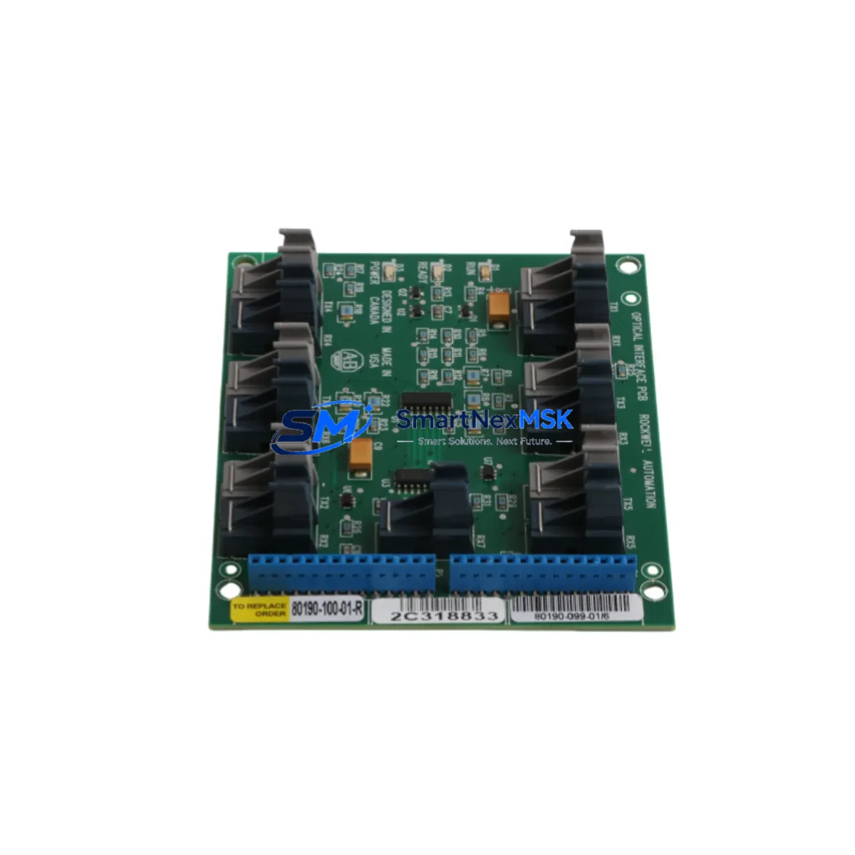
| Part Number | 80190-100-01-R |
| Product Type | PLC Control Board / CPU Board Replacement |
| Compatibility | OEM-compatible; designed as a drop-in replacement for legacy control system boards |
| Backplane Interface | Compatible with original rack/chassis backplane connector pinout |
| Power Requirements | Matches original board power envelope (verify 5 VDC / 24 VDC backplane supply) |
| Communication Ports | Matches original communication interface (RS-232 / RS-485 / proprietary bus — verify per application) |
| Terminal Wiring | Direct wiring-compatible; no field rewiring required under standard replacement conditions |
| Module Addressing | DIP switch / rotary dial addressing — must be set to match original configuration |
| Program Compatibility | Supports re-download of original application program via compatible programming cable |
| Installation Type | Board-level swap; no chassis modification required |
| Pre-Shipment Testing | Full functional test including power-on, I/O continuity, and communication port validation |
| Warranty | 12 months from date of shipment |
| Origin | CN |
| Shipping | In-stock; expedited dispatch available for emergency orders |
Retrofit Planning for Existing Automation Systems
A successful retrofit begins with a thorough site survey. Before ordering the 80190-100-01-R, document the existing rack configuration, including the chassis model, power supply module part number, and the slot assignments of all installed modules. In a typical legacy control cabinet, you may find a mix of discrete input modules, discrete output modules, analog input cards, and a dedicated communication module occupying adjacent slots. Each of these components must be accounted for in the retrofit plan.
The power supply module is a frequent point of failure in aging systems and should be inspected alongside the control board. If the existing power supply shows signs of capacitor aging, output voltage drift, or thermal stress, replacing it concurrently with the 80190-100-01-R will reduce the risk of a repeat failure shortly after the board swap. Similarly, the rack or chassis backplane should be inspected for bent connector pins or oxidation on the edge connector contacts, as these can cause intermittent communication faults that are difficult to diagnose after the new board is installed.
Terminal block assemblies on the I/O modules are another area of concern in long-running systems. Loose or corroded terminal screws can cause field signal errors that may be misattributed to the new control board. A systematic check of all field wiring terminations before powering up the retrofitted system will save significant diagnostic time. If the system includes a programming cable for connecting a laptop to the CPU port — whether a legacy RS-232 null modem cable, a USB-to-DH+ adapter, or a Bluetooth programming adapter — confirm that the cable and associated driver software are functional before beginning the board swap.
For systems that include remote I/O drops connected via a dedicated I/O bus, the remote adapter modules at each drop must be verified to be communicating correctly after the board replacement. In some legacy architectures, the remote I/O scanner configuration is stored on the CPU board itself and must be re-entered or re-downloaded after the swap. Confirm this requirement with the system documentation before proceeding.
If the retrofit is part of a broader migration from a legacy platform to a modern controller, the 80190-100-01-R can serve as an interim solution, stabilizing the existing system while the migration project is planned and executed. This approach allows production to continue without interruption while the new control platform — including updated I/O modules, a modern communication processor, and a revised HMI project — is developed and tested offline.
Downtime Control During System Migration
Minimizing unplanned downtime is the primary objective of any control system retrofit. The 80190-100-01-R is designed to support a rapid board-level swap that can be completed within a planned maintenance window, typically without requiring changes to field wiring, rack configuration, or the application program.
To protect the original program logic, always create a verified backup of the application program before removing the original board. Use the appropriate programming software and cable to upload the program from the existing CPU to a laptop, and confirm that the backup file is complete and readable before proceeding. If the original board is non-functional and a program backup cannot be retrieved from it, check whether a backup copy exists in the site’s document management system or on a previous programming laptop. In some cases, the program may also be recoverable from a connected HMI or SCADA system if the original project files were archived there.
During the physical board swap, follow standard ESD precautions: power down the rack, discharge any residual voltage on the backplane, and handle the replacement board by its edges. After installing the 80190-100-01-R and restoring power, verify that the board initializes correctly and that all I/O modules in the rack are recognized. Download the application program, set the module addressing to match the original configuration, and perform a controlled test of all I/O channels before returning the system to automatic operation.
For critical production lines where even a brief interruption is costly, consider staging the replacement board in advance: configure the addressing, download the program, and verify communication on a test bench before bringing the board to the field. This approach reduces the time the system is offline to the minimum required for the physical swap and reconnection, typically 30 to 60 minutes for an experienced technician.
Maintaining field control continuity during the migration also requires coordination with the operations team. Ensure that all field devices — motors, valves, sensors, and safety interlocks — are in a safe state before powering down the control system, and confirm with the operations supervisor that the system is clear to restart after the retrofit is complete.
Retrofit Support FAQ
Q1: Is the 80190-100-01-R a direct drop-in replacement for the original board?
A: Yes, the 80190-100-01-R is manufactured to match the original board’s electrical specifications, backplane connector pinout, and terminal wiring layout. In most standard replacement scenarios, no field rewiring or chassis modification is required. However, engineers should always verify the module addressing configuration (DIP switches or rotary dials) and confirm that the application program has been backed up before proceeding with the swap.
Q2: What commissioning steps are required after installation?
A: After installing the board and restoring power, verify that the CPU initializes without fault codes, confirm that all I/O modules in the rack are recognized, download the application program using the appropriate programming cable and software, and perform a systematic I/O channel test before returning the system to automatic operation. If the system includes remote I/O drops or a communication processor, verify that all network nodes are communicating correctly before enabling automatic mode.
Q3: Can this board be used as part of a migration from a legacy platform to a modern controller?
A: Yes. The 80190-100-01-R is well-suited as an interim stabilization solution during a phased migration project. It allows the existing production system to continue operating reliably while the new control platform is developed, tested, and validated offline. This approach eliminates the need for a high-risk cutover and gives the engineering team time to complete the migration without production pressure.
Q4: What does the 12-month warranty cover, and what is the process for a warranty claim?
A: The 12-month warranty covers manufacturing defects and functional failures under normal operating conditions from the date of shipment. Each unit is pre-tested before dispatch, and a test report is included with the shipment. To initiate a warranty claim, contact our sales team with the order number, a description of the fault, and any available diagnostic information. We will arrange for a replacement unit to be dispatched promptly to minimize your system downtime.
© 2026 SMARTNEXMSK. All rights reserved.
Original Source: https://smartnexmsk.com
Contact: sales@smartnexmsk.com | +86 18259474341