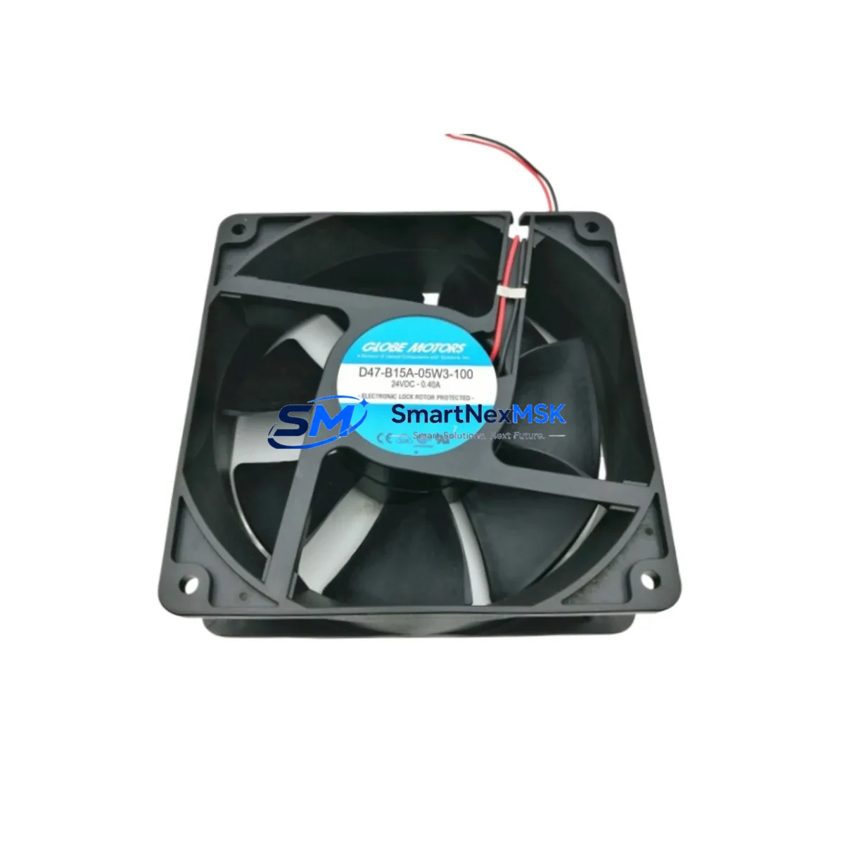
GLOBE MOTORS D47-B15A-05W3-100 Retrofit-Ready Brushless DC Fan for D47 Series Control Systems
The GLOBE MOTORS D47-B15A-05W3-100 is a retrofit-ready brushless DC fan engineered for seamless integration into legacy D47 Series control enclosures, automation cabinets, and industrial cooling assemblies. As original D47-series thermal management components reach end-of-life or become increasingly difficult to source, the D47-B15A-05W3-100 provides a verified drop-in replacement path that preserves existing wiring harnesses, mounting footprints, and connector pinouts — minimizing downtime and eliminating the need for panel redesign.
Whether you are managing a planned upgrade cycle, responding to an unplanned failure, or executing a phased modernization of aging automation infrastructure, the D47-B15A-05W3-100 is stocked and ready to ship from Xiamen with a 12-month warranty covering manufacturing defects and performance conformance.
Upgrade Compatibility Table
| Parameter | D47-B15A-05W3-100 (This Unit) | Retrofit Notes |
|---|---|---|
| Series Compatibility | GLOBE MOTORS D47 Series | Direct replacement for D47-series fan positions |
| Motor Type | Brushless DC (BLDC) | Replaces brushed or earlier BLDC variants in same frame |
| Mounting Interface | Standard D47 flange pattern | No panel modification required; existing hardware reused |
| Connector / Wiring | OEM-compatible pinout | Verify harness polarity before energizing; no re-crimping needed in most cases |
| Supply Voltage | 5 VDC (nominal) | Confirm PSU rail capacity; co-located with logic supply in many D47 cabinets |
| Communication / Control | PWM speed control (where applicable) | Verify PWM signal compatibility with existing controller output card |
| Installation Requirement | Standard screwdriver; no special tooling | Torque to OEM spec; check gasket/seal condition on enclosure |
| Commissioning | Power-on functional test recommended | Monitor RPM feedback signal and thermal sensor output post-installation |
| Warranty | 12 Months | Covers manufacturing defects; pre-shipment functional test included |
Retrofit Planning for Existing Automation Systems
Successful integration of the D47-B15A-05W3-100 into an operating automation environment requires a structured pre-installation review. In most D47-series control cabinets, the fan assembly shares a 5 VDC logic rail with adjacent I/O modules and communication cards. Before removing the legacy unit, engineers should audit the power supply module — typically a DIN-rail mounted DC/DC converter — to confirm available current headroom. If the existing PSU is already operating near capacity due to added I/O expansion modules or a recently installed fieldbus gateway, a parallel PSU upgrade may be advisable.
Terminal block wiring in D47-series enclosures is generally standardized, but aging installations may have accumulated field modifications. Document the existing fan wiring against the original panel drawing before disconnection. In cabinets where a terminal block assembly has been extended or re-labeled over multiple maintenance cycles, cross-reference the as-built drawing rather than the original schematic. Pay particular attention to the tachometer feedback wire if the host controller — often a compact PLC or motion controller — uses fan speed as a thermal interlock condition.
For systems where the D47-series fan is monitored by an HMI panel (touch screen or operator station), verify that the fan status tag in the HMI project maps correctly to the new unit’s feedback signal. In older SCADA or HMI configurations, the fan alarm threshold may be hard-coded to the RPM range of the original component; recalibration of the alarm setpoint in the HMI project may be required after replacement.
If the control cabinet includes a communications module — such as a PROFIBUS DP adapter, DeviceNet scanner, or Modbus RTU gateway — confirm that the fan replacement does not disturb the fieldbus cable routing or termination resistors. Vibration from an improperly seated fan can cause intermittent fieldbus errors that are difficult to diagnose without a protocol analyzer. Secure all cable ties and verify bus termination after installation.
In multi-axis or multi-zone systems, the D47-B15A-05W3-100 may be installed alongside servo drive cooling fans, rack-mount power supplies, or backplane cooling assemblies within the same enclosure. Coordinate the replacement schedule to avoid simultaneous removal of multiple thermal management components, which could cause the enclosure to exceed its thermal rating during the maintenance window.
For legacy systems that include a programmable relay module or safety relay monitoring enclosure temperature, confirm that the interlock logic will not trigger an emergency stop during the fan swap. Where possible, place the affected zone in a maintenance mode or bypass the thermal interlock temporarily under a formal permit-to-work procedure.
Customers upgrading from discontinued D47-series variants should also review the backplane connector and rack guide alignment if the fan is integrated into a modular rack assembly. Dimensional tolerances between production batches can occasionally require minor guide adjustment. A programming cable and laptop with the OEM configuration utility should be on hand during commissioning to read back any fault codes generated during the first power-on cycle.
Downtime Control During System Migration
Minimizing production downtime during a fan replacement on an active control system requires advance preparation and a disciplined execution sequence. The recommended approach is to pre-stage the D47-B15A-05W3-100 alongside all required consumables — including replacement terminal ferrules, cable ties, and a torque screwdriver — before the maintenance window opens. A pre-shipment functional test is performed on every unit prior to dispatch, reducing the risk of a DOA component extending the outage.
Where the control system supports hot-standby or redundant cooling paths, the replacement can often be performed without a full system shutdown. In single-fan configurations, coordinate with the process team to schedule the swap during a planned production break or shift changeover. Keep the original fan intact and tested until the replacement is confirmed operational — do not discard the legacy unit until the new fan has completed at least one full thermal cycle under load.
Preserve the original PLC program and HMI project by creating a verified backup before any maintenance activity. If the fan replacement is part of a broader control system upgrade — for example, migrating from an older CPU module to a current-generation controller — sequence the fan replacement as the final step, after all program logic has been validated on the new hardware. This ensures that any fan-related interlock logic is tested against the production program rather than a development version.
Post-installation, monitor the enclosure temperature via the HMI or a portable thermal camera for the first 30 minutes of operation. Confirm that the fan RPM feedback signal is within the expected range and that no thermal alarms are active. Document the replacement in the equipment maintenance log, including the date, technician name, and the serial number of the installed D47-B15A-05W3-100 unit for warranty tracking purposes.
Retrofit Support FAQ
Q1: Is the D47-B15A-05W3-100 a direct drop-in replacement for all D47 Series fan positions?
In the majority of D47-series enclosures, the D47-B15A-05W3-100 is a direct mechanical and electrical replacement. Verify the mounting flange pattern, connector pinout, and supply voltage against your panel drawing before ordering. For non-standard or field-modified installations, contact sales@smartnexmsk.com with your panel drawing for a compatibility confirmation.
Q2: What commissioning steps are required after installation?
After mechanical installation and wiring reconnection, perform a controlled power-on with the enclosure door open and monitor the fan for correct rotation direction, audible abnormalities, and RPM feedback signal. If the host controller generates a fan fault alarm on first power-on, check the tachometer signal wire continuity and confirm the alarm threshold setting in the controller configuration. Clear any latched faults before returning the system to automatic mode.
Q3: How is wiring compatibility verified for aging D47-series panels?
Obtain the as-built wiring diagram for the specific panel. Compare the existing harness connector pinout against the D47-B15A-05W3-100 datasheet. Pay particular attention to the tachometer output wire (if present), the PWM control input (if used), and the ground reference. If the original harness uses non-standard wire colors due to field modifications, use a continuity tester to map each wire before reconnection.
Q4: What does the 12-month warranty cover, and how is a claim initiated?
The 12-month warranty covers manufacturing defects in materials and workmanship, including motor bearing failure, winding faults, and connector defects under normal operating conditions. Each unit undergoes a pre-shipment functional test. To initiate a warranty claim, contact sales@smartnexmsk.com with the unit serial number, purchase date, and a description of the fault. Replacement units are dispatched upon fault confirmation.
© 2026 SMARTNEXMSK. All rights reserved.
Original Source: https://smartnexmsk.com
Contact: sales@smartnexmsk.com | +86 18259474341