HIWIN QSPT0400 TAB217-1/PC2-LF Retrofit-Ready Thermal Assembly for QSPT Series Control Systems
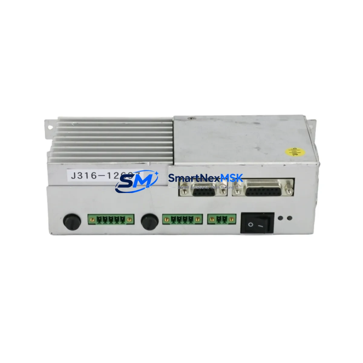
The HIWIN QSPT0400 TAB217-1/PC2-LF is a precision thermal assembly module engineered for direct-fit replacement and system-level retrofit within HIWIN QSPT0400 series linear motion platforms. As legacy QSPT0400 units approach end-of-service life and OEM spare parts become increasingly scarce, this assembly provides a verified compatibility path for maintenance engineers, system integrators, and automation upgrade teams managing aging production lines. Cross-reference part numbers 2L08-050043-11, 2L81-050043-11, and 0021-09914 are fully supported, enabling drop-in substitution without mechanical rework or custom fabrication.
This thermal assembly is designed to maintain stable operating temperatures across the QSPT0400 linear module’s drive and guide components during continuous-duty cycles. Proper thermal management is critical in high-throughput automation environments where sustained axis motion, servo drive loading, and ambient temperature variation can accelerate wear on ball screw assemblies, linear guideways, and encoder feedback systems. The TAB217-1/PC2-LF configuration addresses these demands with materials and geometry matched to the original HIWIN specification.
Upgrade Compatibility Table
| Parameter | Details |
|---|---|
| Compatible Series | HIWIN QSPT0400 |
| Replaces Part Numbers | 2L08-050043-11, 2L81-050043-11, 0021-09914 |
| Mounting Interface | Direct-fit to QSPT0400 module housing; no adapter required |
| Communication Compatibility | Passive thermal component; compatible with all QSPT0400 drive configurations including EtherCAT and MECHATROLINK-III servo systems |
| Installation Requirement | Standard HIWIN torque spec; refer to QSPT0400 maintenance manual for fastener sequence |
| Replacement Recommendation | Replace at scheduled PM interval or upon detection of thermal anomaly in axis drive data |
| Commissioning Notes | Verify axis homing, encoder reference, and thermal sensor feedback post-installation |
| Warranty | 12 Months from date of shipment |
Retrofit Planning for Existing Automation Systems
When planning a retrofit around the QSPT0400 TAB217-1/PC2-LF, engineers must evaluate the full mechanical and electrical context of the affected axis. In a typical HIWIN-based linear motion system, the QSPT0400 module operates in conjunction with a servo drive unit, a motion controller, and a feedback encoder — all of which must remain functional and correctly configured throughout the replacement procedure.
Before disassembly, confirm that the servo drive powering the affected axis is safely inhibited and that the HIWIN servo amplifier’s enable signal is de-asserted. In systems using a HIWIN D1 series servo drive or equivalent third-party amplifier, verify that the drive’s fault log is cleared and that no persistent thermal fault codes are present. If the system uses a multi-axis controller such as a HIWIN motion controller or a third-party EtherCAT master, ensure the affected axis is placed in a safe, parked state before proceeding.
Inspect the QSPT0400 module’s ball screw support bearing block and linear guideway carriage for signs of secondary thermal damage before installing the new TAB217-1/PC2-LF assembly. In cases where the original thermal assembly failed due to sustained overload, the adjacent HIWIN linear guideway (HG or EG series) and ball screw nut may also require inspection or replacement. Document the pre-removal condition of all terminal connections, cable routing, and sensor wiring to ensure accurate reassembly.
For systems that include a HIWIN absolute encoder or external linear scale, confirm that the encoder reference position is recorded before axis disassembly. After installation of the new thermal assembly, re-establish the encoder home reference and verify axis travel limits within the motion controller. In multi-axis gantry or Cartesian configurations, cross-check the geometric alignment of the replaced axis against the reference axis using a dial indicator or laser alignment tool.
Systems integrating HIWIN QSPT0400 modules with third-party PLCs via pulse-direction or analog command interfaces should verify that the command signal integrity is maintained after reassembly. If the system uses a fieldbus protocol such as PROFIBUS, DeviceNet, or CANopen for distributed I/O, confirm that the I/O module addresses and network node assignments are unchanged. In installations where a HIWIN HMI or third-party operator panel displays axis status, verify that the thermal status display and alarm thresholds are correctly mapped after the retrofit is complete.
Where the retrofit is part of a broader control cabinet upgrade — for example, replacing an aging servo drive rack with a current-generation HIWIN servo system — plan for the sequential replacement of power supply modules, servo amplifier units, and communication interface cards before addressing mechanical components. This sequencing minimizes the risk of introducing new faults during the mechanical retrofit phase.
Downtime Control During System Migration
Minimizing unplanned downtime during a QSPT0400 thermal assembly replacement requires a structured pre-shutdown checklist and a clearly defined restoration sequence. Begin by backing up the motion controller’s program logic, axis parameter tables, and communication configuration to an offline storage device. For systems using HIWIN’s proprietary motion programming environment or a third-party IEC 61131-3 compliant PLC, ensure that the program backup includes all axis-specific tuning parameters, including velocity feedforward, position loop gain, and friction compensation values.
Schedule the replacement during a planned maintenance window and pre-stage all required tools, torque specifications, and the replacement TAB217-1/PC2-LF assembly before initiating shutdown. Confirm that a spare HIWIN encoder cable and terminal block connector set are available on-site to address any incidental damage discovered during disassembly. Having these components staged in advance eliminates secondary delays caused by parts procurement during an active maintenance window.
After installation, perform a controlled power-up sequence: energize the control power supply first, verify communication link establishment between the motion controller and servo drive, then enable the servo axis in jog mode at reduced velocity before returning to automatic program execution. Monitor the axis thermal sensor data during the first production cycle to confirm that the new TAB217-1/PC2-LF assembly is performing within the expected temperature range. Document the completed retrofit in the machine maintenance log, including the installation date, technician name, and the replaced part numbers for warranty tracking purposes.
All units supplied by SMARTNEXMSK are subject to pre-shipment functional inspection and are covered by a 12-month warranty from the date of shipment. In-stock availability supports rapid dispatch to minimize the impact of unplanned failures on production continuity.
Retrofit Support FAQ
Q: Is the QSPT0400 TAB217-1/PC2-LF a direct replacement for part numbers 2L08-050043-11 and 2L81-050043-11?
A: Yes. The TAB217-1/PC2-LF is a verified direct-fit replacement for both 2L08-050043-11 and 2L81-050043-11, as well as cross-reference 0021-09914. No mechanical modification or adapter hardware is required for installation on a standard QSPT0400 module housing.
Q: What commissioning steps are required after installing the new thermal assembly?
A: After mechanical installation, verify that all fasteners are torqued to the HIWIN QSPT0400 specification. Re-establish the servo axis encoder home reference, confirm axis travel limit settings in the motion controller, and perform a low-speed jog cycle before returning the axis to automatic operation. Monitor thermal sensor feedback during the first production run to confirm normal operating temperature.
Q: How should I verify wiring and terminal connections during the replacement?
A: Document all terminal connections, cable routing, and sensor wiring before disassembly using photographs or a wiring diagram. The TAB217-1/PC2-LF uses the same connector interface as the original assembly, so no rewiring is required. After installation, verify continuity on all sensor and power connections before energizing the axis.
Q: What does the 12-month warranty cover, and how is it validated?
A: The 12-month warranty covers manufacturing defects and functional failures under normal operating conditions from the date of shipment. Warranty claims are supported by the shipment invoice and the part number documentation provided with each unit. Pre-shipment inspection records are available upon request. Contact sales@smartnexmsk.com for warranty support.
© 2026 SMARTNEXMSK. All rights reserved.
Original Source: https://smartnexmsk.com
Contact: sales@smartnexmsk.com | +86 18259474341