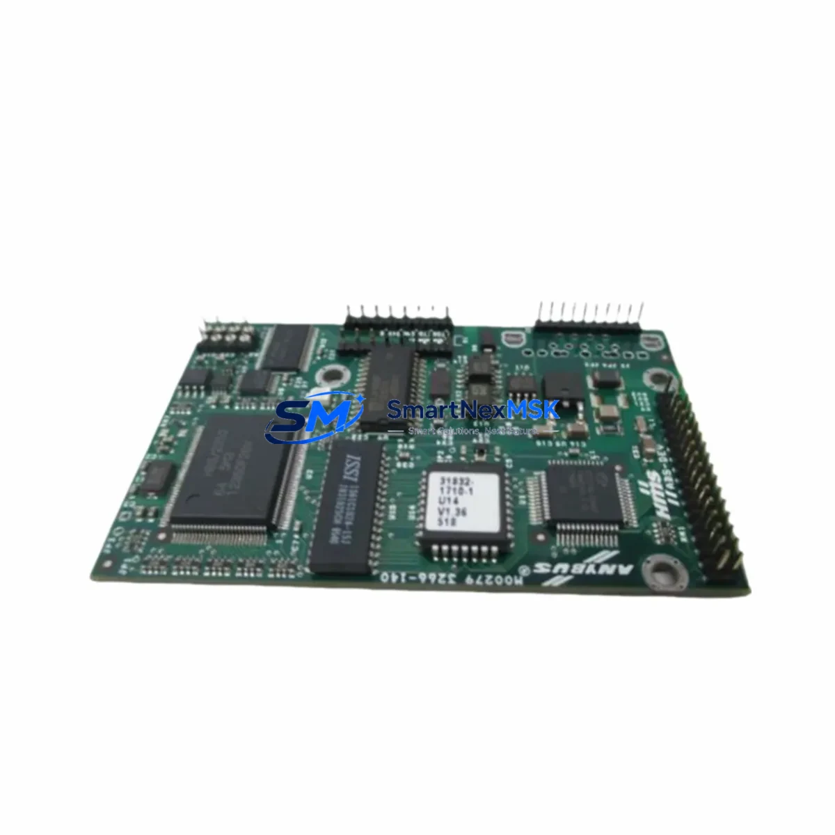
HMS M00279 3266-140 Retrofit-Ready Gateway for Anybus Control Systems
The HMS M00279 3266-140 is a retrofit-ready industrial communication gateway designed for seamless integration into existing Anybus-based control architectures. Whether you are replacing an end-of-life communication board, upgrading a legacy PLC cabinet, or migrating from an obsolete fieldbus protocol to modern Ethernet-based networks, the M00279 3266-140 provides a verified, drop-in compatible solution backed by 12 months of warranty coverage and pre-shipment functional testing.
HMS Networks has long been the standard for multi-protocol communication in industrial automation. The M00279 3266-140 continues this tradition by supporting a wide range of fieldbus and industrial Ethernet protocols, making it an ideal candidate for brownfield retrofit projects where maintaining control continuity is critical. Engineers working on control cabinet upgrades, I/O expansion projects, or communication link migrations will find this module to be a reliable, specification-matched replacement for discontinued Anybus variants.
Upgrade Compatibility Table
| Parameter | Details |
|---|---|
| SKU / Part Number | M00279 3266-140 |
| Brand / Manufacturer | HMS Networks (Sweden) |
| Product Series | Anybus Communication Gateway Series |
| Form Factor / Installation | DIN-rail or panel-mount; compatible with standard Anybus backplane slots |
| Communication Compatibility | PROFIBUS DP, DeviceNet, CANopen, Modbus RTU/TCP, EtherNet/IP, PROFINET (series-dependent) |
| Replacement Suitability | Direct replacement for discontinued M00279-series Anybus boards in legacy PLC/DCS cabinets |
| Terminal / Connector Interface | Standard Anybus terminal block and D-sub connector layout; verify pinout against original wiring diagram |
| Commissioning Notes | Node address, baud rate, and network parameters must be reconfigured after installation; use Anybus Configuration Manager or equivalent |
| Firmware / Software | Compatible with HMS Anybus Configuration Manager; check firmware version alignment with host PLC |
| Warranty | 12-Month Warranty — all units tested prior to shipment |
Retrofit Planning for Existing Automation Systems
Successful retrofit of the HMS M00279 3266-140 into an existing control system requires a structured pre-installation review. Before removing the original communication board, engineers should document the current network topology, including all connected field devices, node addresses, and baud rate settings. In systems where the Anybus module interfaces with a Siemens S7-300 or S7-400 PLC via PROFIBUS DP, the GSD file associated with the original module must be retained and cross-referenced against the replacement unit’s device description file to ensure seamless re-integration without reprogramming the master controller.
In control cabinets where the M00279 3266-140 operates alongside an Anybus Communicator AC series or an Anybus X-gateway, the backplane slot assignment and module addressing must be verified before power-up. Systems using a Beckhoff CX series controller or an Allen-Bradley ControlLogix chassis as the network master may require an updated EDS file or GSD file import into the engineering workstation before the replacement module is recognized on the network.
For installations involving I/O expansion — such as adding remote I/O nodes via a Wago 750 series fieldbus coupler or a Phoenix Contact Inline controller — the M00279 3266-140 must be configured to accommodate the expanded node count and updated I/O mapping tables. Power supply capacity in the control cabinet should also be reviewed: the existing Siemens SITOP PSU or Phoenix Contact QUINT power supply must provide sufficient current headroom for the replacement module plus any additional I/O nodes being commissioned during the same maintenance window.
HMI screen updates are frequently overlooked during communication board replacements. If the control system includes a Siemens TP700 Comfort Panel or a Weintek cMT series HMI, the tag database and communication driver settings must be updated to reflect any changes in the PLC memory map or network address resulting from the module swap. Failure to update HMI communication parameters is one of the most common causes of extended downtime during retrofit projects.
Programming cable access is another critical consideration. If the host PLC requires a firmware update or program modification as part of the retrofit, ensure that a compatible Siemens PC Adapter USB or Profibus programming cable is available on-site before the maintenance window begins. All program backups should be completed and verified before the original module is removed from service.
Downtime Control During System Migration
Minimizing production downtime during a communication board replacement requires careful pre-staging and a clearly defined rollback plan. Before the maintenance window opens, the replacement HMS M00279 3266-140 should be pre-configured off-line using the Anybus Configuration Manager, with all network parameters — node address, baud rate, protocol selection, and I/O data mapping — set to match the original module’s configuration. This allows the physical swap to be completed in minutes rather than hours.
The original PLC program should be backed up to both the engineering workstation and an offline storage device before any hardware is disturbed. If the host controller is a Siemens S7 series PLC, a full online backup via STEP 7 or TIA Portal should be completed and verified. For Allen-Bradley systems, an RSLogix 5000 or Studio 5000 project archive should be saved and confirmed readable before the maintenance window begins.
During the physical swap, all terminal wiring should be photographed and labeled before disconnection. The M00279 3266-140’s terminal block layout is designed to match the Anybus series standard, but field wiring variations introduced during previous maintenance cycles may require minor adaptation. After reconnection, a point-by-point I/O verification should be performed before returning the system to automatic mode, confirming that all field signals — including digital inputs, analog outputs, and communication status indicators — are reading correctly in the PLC and HMI.
If the system cannot tolerate a full shutdown, consider a staged migration approach: bring the replacement module online in parallel with the original unit on a test network segment, verify all communication links and I/O data integrity, then perform the final cutover during a scheduled low-production period. This approach is particularly effective in continuous process environments where even brief interruptions to the control loop can trigger safety shutdowns or product quality deviations.
Retrofit Support FAQ
Q1: Is the HMS M00279 3266-140 a direct drop-in replacement for my existing Anybus communication board?
In most cases, yes. The M00279 3266-140 is designed to be physically and electrically compatible with standard Anybus series slots. However, you should verify the connector type, terminal block pinout, and supported protocol against your original module’s datasheet before installation. If your original module used a non-standard firmware configuration, reconfiguration via Anybus Configuration Manager will be required after the swap.
Q2: What commissioning steps are required after installing the replacement module?
After physical installation, you must reconfigure the node address, baud rate, and protocol parameters using the Anybus Configuration Manager or the host PLC’s network configuration tool. Verify that the GSD or EDS file loaded in the PLC master matches the replacement module’s device description. Perform a full I/O scan and confirm all field device communication links are active before returning the system to automatic operation.
Q3: How do I verify wiring compatibility before removing the original module?
Document all terminal connections on the original module using photographs and a wiring diagram before disconnection. Compare the terminal block layout of the M00279 3266-140 against the original module’s installation manual. Pay particular attention to power supply terminals, shield grounding connections, and any jumper settings that control termination resistance on PROFIBUS or DeviceNet segments.
Q4: What does the 12-month warranty cover, and how are units tested before shipment?
All HMS M00279 3266-140 units supplied by SMARTNEXMSK are functionally tested prior to shipment, including communication link verification and power-on self-test confirmation. The 12-month warranty covers manufacturing defects and functional failures under normal operating conditions. Units showing physical damage caused by incorrect installation, overvoltage, or environmental exposure outside the specified operating range are not covered. For warranty claims or technical support, contact sales@smartnexmsk.com.
© 2026 SMARTNEXMSK. All rights reserved.
Original Source: https://smartnexmsk.com
Contact: sales@smartnexmsk.com | +86 18259474341