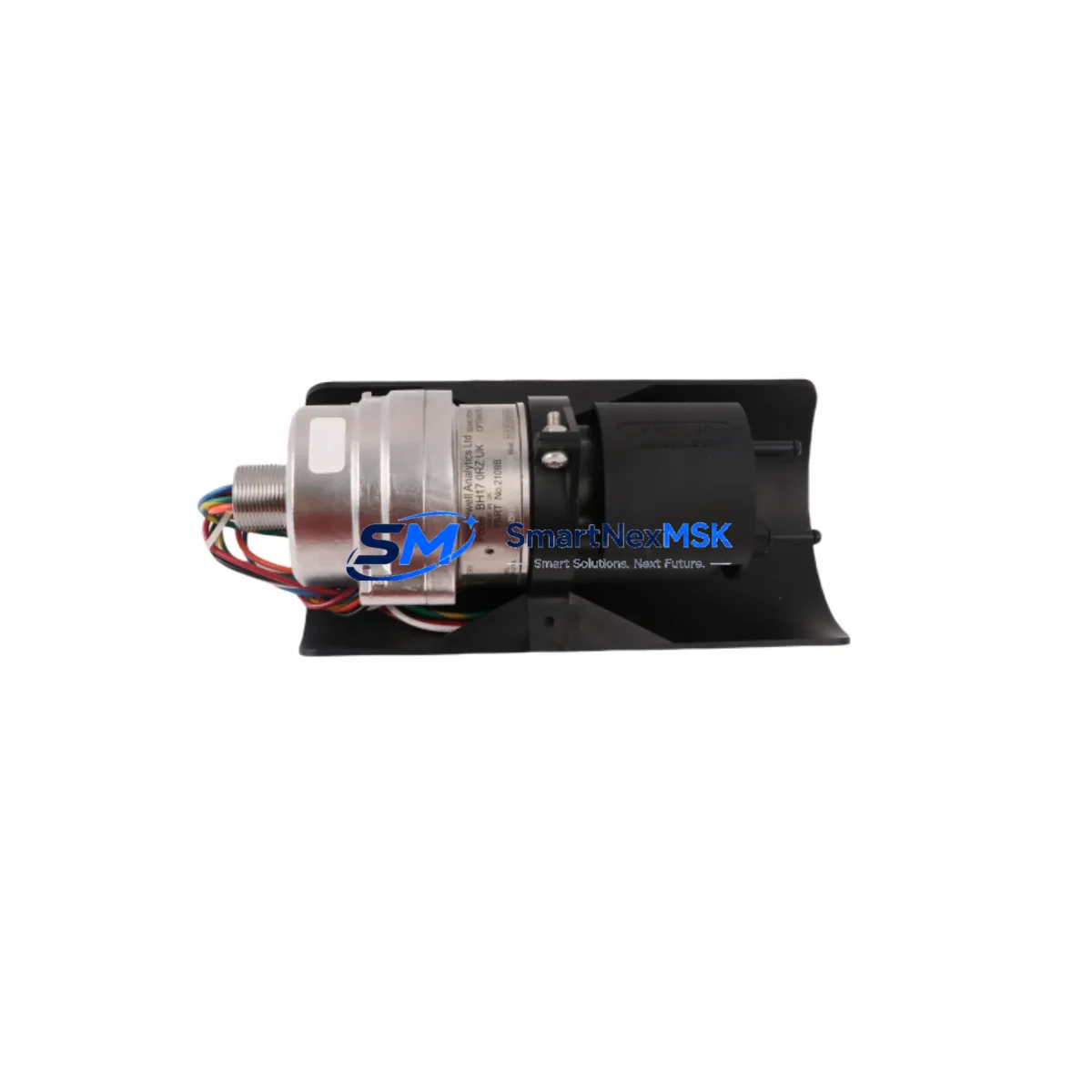
Honeywell 2108B2001N Maintenance-Ready Spare Optima Plus Automation
The Honeywell 2108B2001N is a factory-original spare unit for the Searchpoint Optima Plus fixed-point infrared gas detector series — one of the most widely deployed combustible gas detection platforms in oil & gas, petrochemical, offshore, and heavy industrial facilities worldwide. When a gas detection point goes offline, the risk to personnel safety and regulatory compliance escalates immediately. Stocking the 2108B2001N as a maintenance-ready spare is the most direct strategy for minimizing unplanned downtime and restoring continuous monitoring capability without waiting on extended lead times.
Designed for maintenance engineers and procurement teams managing aging or active Optima Plus installations, this unit provides a direct, plug-compatible replacement for failed or end-of-life detector heads. The 2108B2001N retains full compatibility with the Optima Plus series junction boxes, signal conditioning electronics, and 4–20 mA output loops — eliminating the need for rewiring or recalibration of the host control system during a swap. Every unit is tested prior to dispatch and ships with a 12-month warranty covering manufacturing defects and functional performance.
For facilities running Honeywell’s Safety Manager, FSC, or third-party DCS/PLC platforms with Modbus or HART integration, the 2108B2001N integrates without protocol changes, preserving existing alarm setpoints and loop configurations. This makes it equally suitable for planned preventive maintenance rotations and emergency corrective replacements.
Spare Maintenance Table
| Parameter | Specification |
|---|---|
| Part Number / SKU | 2108B2001N |
| Brand | Honeywell Analytics |
| Series | Searchpoint Optima Plus |
| Product Type | Fixed-Point Infrared Gas Detector |
| Detection Principle | Non-Dispersive Infrared (NDIR) |
| Target Gas | Combustible Hydrocarbons (0–100% LEL) |
| Output Signal | 4–20 mA (linear), HART optional |
| Supply Voltage | 18–32 V DC |
| Power Consumption | ≤ 3.5 W (steady state) |
| Ingress Protection | IP66 / IP67 |
| Explosion Protection | ATEX / IECEx Zone 1 & Zone 2 |
| Operating Temperature | -40°C to +65°C |
| Compatibility | Optima Plus junction boxes, Optima Plus signal conditioners, existing 4–20 mA loops |
| Country of Origin | United Kingdom |
| Warranty | 12 Months |
| Condition | Original New / Tested Before Shipment |
| Maintenance Recommendation | Replace every 5 years or upon fault indication; bump test every 6 months |
Maintenance Planning for Continuous Operation
A gas detector replacement is rarely an isolated task. When a 2108B2001N is being swapped in the field, a disciplined maintenance engineer will use the opportunity to inspect and verify the condition of all associated components in the same detection loop and control cabinet. Neglecting adjacent components is a common cause of repeat callouts and premature failures after a detector replacement.
Begin with the Optima Plus junction box — inspect terminal blocks for corrosion, moisture ingress, and loose connections. The junction box houses the signal conditioning board; if the board shows signs of heat stress or contamination, replace it alongside the detector head to avoid a secondary fault within weeks. Check the cable glands and conduit seals for integrity, as IP66/67 protection is only as good as the installation sealing.
Verify the 24 V DC field power supply feeding the detector loop. Voltage drop across long cable runs can push supply voltage below the 18 V minimum threshold, causing intermittent faults that are difficult to diagnose remotely. Use a calibrated multimeter at the detector terminals, not at the panel. If the supply is shared with other instruments, check the DIN rail power supply module (such as a Honeywell or Phoenix Contact 24 V unit) for output ripple and load capacity.
Inspect the 4–20 mA signal loop back to the safety controller or DCS analog input card. Confirm loop resistance is within specification and that the analog input module on the host system — whether a Honeywell FSC I/O card, a Safety Manager analog input board, or a third-party PLC AI module — is reading correctly at 4 mA (0% LEL) before reconnecting the new detector. A faulty AI channel will cause the replacement detector to appear defective.
If the installation uses HART communication, verify that the HART modem or multiplexer is polling the new device correctly after replacement. Update the device descriptor (DD) file in the asset management system if the firmware revision has changed. For sites using Modbus RTU or Profibus DP integration via a gateway, confirm the device address and register mapping remain unchanged after the swap.
Check the alarm relay outputs at the controller — typically a dedicated safety relay module or a relay output card — to confirm that alarm thresholds (typically 10% LEL for Level 1, 20% LEL for Level 2) are correctly configured and that the relay contacts are not worn. Relay contact resistance above 0.5 Ω on a safety-critical output warrants replacement of the relay module.
Finally, inspect the local indicator or remote HMI panel displaying gas concentration. If the site uses a Honeywell Touchpoint Plus or a third-party gas controller panel, confirm that the channel is re-enabled and that the display reads correctly after the new 2108B2001N is powered up and stabilized. A 30-minute warm-up period is recommended before performing a bump test or zero/span calibration.
Site Replacement Workflow
Step 1 — Permit and Isolation: Obtain a hot work or confined space permit as applicable. Isolate the detector loop at the field junction box, not at the panel, to avoid triggering a system fault alarm during the swap. Notify the control room and log the maintenance activity in the CMMS.
Step 2 — Remove the Existing Unit: Disconnect the 2108B2001N from the junction box terminals. Note the wiring configuration and photograph terminal connections before removal. If the existing unit is an older Optima Plus variant (e.g., 2108B1001N or earlier suffix), confirm that the replacement unit’s connector and mounting pattern are compatible — the Optima Plus series maintains backward mechanical compatibility across most revisions.
Step 3 — Inspect and Clean: Clean the junction box interior with dry compressed air. Inspect the optical window area on the new unit for transit damage. Do not touch the optical surfaces.
Step 4 — Install and Wire: Mount the 2108B2001N, reconnect terminals per the original wiring diagram, and torque cable gland to the manufacturer’s specification. Restore power and allow a 30-minute stabilization period.
Step 5 — Functional Verification: Apply a certified calibration gas at the specified concentration to verify the 4–20 mA output tracks correctly. Confirm alarm relay activation at the programmed setpoints. Update the maintenance record and calibration certificate in the CMMS.
Step 6 — Return to Service: Re-enable the channel at the controller, confirm the HMI displays a healthy status, and close the maintenance permit. Schedule the next bump test within 6 months per site procedures.
Spare Parts Support FAQ
Q1: Is the 2108B2001N a direct drop-in replacement for earlier Optima Plus detector variants?
Yes. The 2108B2001N is mechanically and electrically compatible with the Optima Plus junction box and signal conditioning assembly. It uses the same 4–20 mA output loop and mounting interface as earlier Optima Plus variants, making it a direct field replacement without rewiring or reconfiguration of the host control system.
Q2: How do you verify compatibility before shipment?
Each unit undergoes a pre-shipment functional test covering output signal linearity, power consumption, and alarm relay response. The part number and revision are confirmed against the order before dispatch. We recommend customers provide their existing unit’s label photograph or full part number string when ordering to allow cross-reference verification.
Q3: What is the recommended spare stock strategy for a multi-point Optima Plus installation?
For installations with 10 or more Optima Plus detection points, we recommend maintaining a minimum of 10% of the installed base as on-site hot spares — typically 1–2 units for smaller installations, 3–5 for larger ones. This supports both planned preventive maintenance rotations (typically every 5 years) and emergency corrective replacements without waiting on international shipping lead times.
Q4: What does the 12-month warranty cover?
The 12-month warranty covers manufacturing defects, component failures under normal operating conditions, and functional performance deviations from the published specification. It does not cover damage resulting from incorrect installation, exposure to gases or environments outside the rated specification, or physical impact. Warranty claims are supported with a replacement unit dispatched after fault confirmation.
© 2026 SMARTNEXMSK. All rights reserved.
Original Source: https://smartnexmsk.com
Contact: sales@smartnexmsk.com | +86 18259474341