HVA 11210-0203RS-001 Retrofit-Ready Gate Valve for RS Series Control Systems
The HVA 11210-0203RS-001 is a precision-engineered, retrofit-ready gate valve designed as a direct replacement and upgrade solution for RS Series pipeline and process control systems. Whether you are managing a scheduled maintenance overhaul, responding to an unexpected valve failure, or executing a planned system modernization, this unit delivers the dimensional accuracy, material compatibility, and pressure rating required to restore or enhance your existing installation without structural modification.
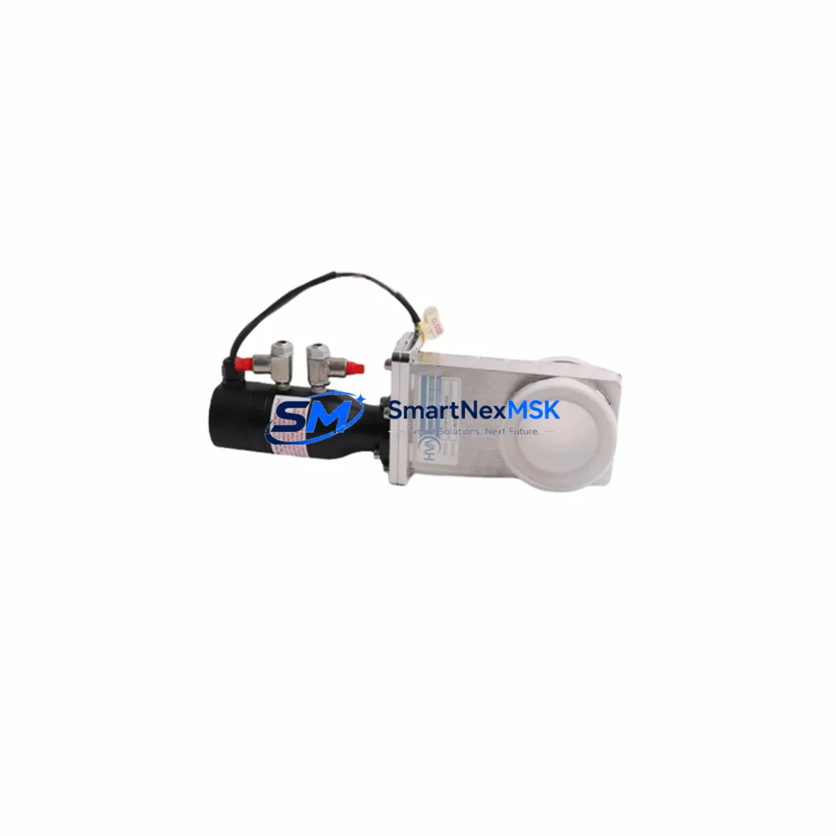
Manufactured to HVA’s industrial-grade specifications, the 11210-0203RS-001 features a full-bore stainless steel body with standardized end connections that align with RS Series pipeline flanges and threaded interfaces. The valve’s actuator-ready stem design supports both manual handwheel operation and direct coupling to pneumatic or electric actuators, making it suitable for both manual control panels and automated process lines. Its compact form factor is engineered to fit within standard control cabinet and skid-mounted valve manifold configurations without requiring additional bracket modifications.
For facilities operating legacy RS Series systems where original HVA gate valves have reached end-of-life or have been discontinued, the 11210-0203RS-001 provides a verified replacement path. Procurement teams and maintenance engineers can source this unit as a like-for-like substitute, eliminating the need for costly piping rework or system redesign. The valve ships pre-tested and ready for installation, with full dimensional documentation available upon request to support pre-installation verification against existing P&ID drawings.
Upgrade Compatibility Table
| Parameter | Details |
|---|---|
| SKU / Part Number | 11210-0203RS-001 |
| Brand | HVA |
| Compatible Series | RS Series Pipeline & Process Control Systems |
| Valve Type | Gate Valve (Full Bore) |
| Body Material | Stainless Steel (SS316 / SS304 per application) |
| End Connection | Flanged / Threaded — RS Series Standard Interface |
| Actuator Compatibility | Manual Handwheel; Pneumatic / Electric Actuator Ready |
| Pressure Rating | Per RS Series system specification (confirm with P&ID) |
| Installation Requirement | Drop-in replacement; no piping modification required |
| Replacement Scope | Direct substitute for discontinued RS Series HVA gate valves |
| Commissioning Note | Verify torque spec, packing gland adjustment, and leak test post-install |
| Origin | China (Xiamen) |
| Warranty | 12 Months from date of shipment |
Retrofit Planning for Existing Automation Systems
Integrating the HVA 11210-0203RS-001 into an existing RS Series installation requires a structured pre-retrofit assessment to ensure seamless compatibility across all connected system components. Before commencing valve replacement, maintenance teams should audit the full valve train, including upstream and downstream isolation valves, actuator assemblies, and any associated positioners or limit switch boxes that interface with the process control system.
In automated pipeline systems, the gate valve typically operates in conjunction with a pneumatic actuator and a solenoid valve manifold. When replacing the 11210-0203RS-001, verify that the actuator’s air supply connections, spring return configuration, and fail-safe position (fail-open or fail-close) match the original design intent documented in the control system’s functional specification. If the existing actuator is a legacy model that has also reached end-of-life, consider simultaneously upgrading to a current-generation HVA RS Series pneumatic actuator to avoid a secondary maintenance event within a short interval.
For systems where the gate valve is monitored via a distributed control system (DCS) or SCADA platform, the limit switch feedback signals — typically 4–20 mA or discrete dry contact — must be re-verified after installation. Confirm that the new valve’s stem travel matches the calibrated range of the existing position transmitter or limit switch box. In installations using a valve positioner, recalibrate the positioner’s zero and span settings against the new valve’s mechanical travel limits before returning the loop to automatic control mode.
Piping systems that incorporate a valve manifold block, pressure gauge assembly, or inline strainer upstream of the gate valve should be inspected during the retrofit window. This is an appropriate time to replace any worn gaskets in the flange connections, inspect the inline Y-strainer or basket strainer for fouling, and verify the integrity of the pipe support brackets adjacent to the valve. If the system uses a manual bypass valve arrangement, confirm that the bypass valve — often a smaller-bore HVA ball valve or needle valve from the same RS Series product family — is fully operational before isolating the main gate valve for replacement.
Control cabinet wiring associated with the valve’s solenoid coil or actuator feedback should be documented and tagged before disconnection. In older installations, terminal block labeling may have degraded; re-label all terminals using the current I/O list from the DCS or PLC panel documentation. If the control system uses a remote I/O module or a fieldbus-connected valve island, confirm that the device address and communication parameters are recorded before powering down the field device segment.
Downtime Control During System Migration
Minimizing process downtime during gate valve replacement is a primary concern for facilities operating continuous or semi-continuous production lines. The HVA 11210-0203RS-001’s drop-in dimensional compatibility with RS Series installations is specifically designed to reduce the mechanical replacement window to the shortest practical duration.
Prior to the planned maintenance window, stage all required materials at the work site: the replacement valve, new flange gaskets, fastener sets, actuator coupling hardware, and any required packing gland components. Confirm that the isolation valves upstream and downstream of the replacement valve are fully functional and capable of achieving a positive shutoff. If the upstream or downstream isolation valves are also legacy RS Series units showing signs of wear, schedule their inspection or replacement during the same maintenance window to avoid a repeat shutdown.
For systems where a full process shutdown is not feasible, evaluate whether a hot-tap or line-stop procedure is applicable based on the fluid service, pressure, and temperature conditions. In lower-pressure utility services, a temporary bypass spool piece may allow the main process line to remain in service while the gate valve is replaced on the isolated branch.
After mechanical installation, conduct a hydrostatic or pneumatic leak test at the valve body and flange connections before restoring process flow. For automated valve applications, perform a full stroke test — open, close, and intermediate position — to verify actuator travel, limit switch operation, and positioner calibration before returning the valve to automatic control. Document the commissioning results in the plant’s maintenance management system (CMMS) and update the as-built P&ID if any dimensional or configuration changes were made during the retrofit.
All HVA 11210-0203RS-001 units supplied by SMARTNEXMSK are covered by a 12-month warranty from the date of shipment, covering manufacturing defects in materials and workmanship. Each unit undergoes pre-shipment functional testing and is shipped with a test certificate. Inventory is maintained in Xiamen for prompt dispatch, with typical lead times of 3–7 business days for standard orders.
Retrofit Support FAQ
Q1: Is the HVA 11210-0203RS-001 a direct drop-in replacement for the original RS Series gate valve?
Yes. The 11210-0203RS-001 is dimensionally compatible with the original HVA RS Series gate valve installation envelope, including face-to-face length, flange bolt circle, and stem height. No piping modification is required for a standard replacement. Confirm the end connection standard (ANSI/DIN/JIS) against your existing flange specification before ordering.
Q2: What commissioning steps are required after installation?
After mechanical installation and flange bolt torquing to specification, perform a leak test at the body and packing gland. For actuated versions, verify actuator air supply pressure, confirm limit switch operation at both end positions, and recalibrate any associated positioner. Return the valve to service only after a successful full-stroke test and leak-free confirmation.
Q3: Can this valve be used with an electric actuator instead of a pneumatic actuator?
Yes. The 11210-0203RS-001 stem is compatible with both pneumatic and electric actuator mounting configurations using the standard ISO 5211 actuator mounting flange. Confirm the actuator’s output torque rating against the valve’s required operating torque at maximum differential pressure before selection.
Q4: What does the 12-month warranty cover, and how is a warranty claim processed?
The 12-month warranty covers manufacturing defects in materials and workmanship from the date of shipment. It does not cover damage resulting from improper installation, operation outside rated conditions, or unauthorized modification. To initiate a warranty claim, contact SMARTNEXMSK with the order reference, shipment date, and a description of the defect. Replacement units or credit will be arranged upon verification.
© 2026 SMARTNEXMSK. All rights reserved.
Original Source: https://smartnexmsk.com
Contact: sales@smartnexmsk.com | +86 18259474341