IEE 03601-54-080 Maintenance-Ready Spare for FLIP Series Automation
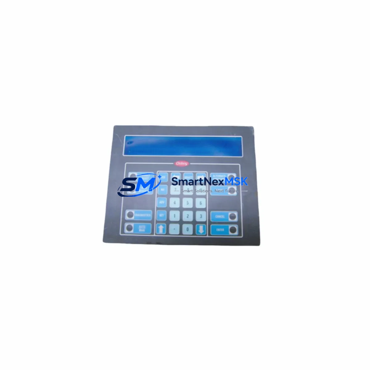
The IEE 03601-54-080 (cross-reference: 03601-34-080) is an original vacuum fluorescent display (VFD) panel module from IEE’s FLIP Series — a proven display technology widely deployed in industrial automation HMI panels, CNC operator stations, process control consoles, and legacy SCADA front-ends. Sourced as a verified original spare, this unit is tested prior to shipment and backed by a 12-month warranty, making it a reliable choice for maintenance engineers managing aging control systems where display panel failures directly translate to unplanned downtime.
For maintenance and procurement engineers, the IEE 03601-54-080 addresses one of the most common failure modes in legacy operator interfaces: VFD panel degradation caused by segment burnout, dimming, or complete display failure. Replacing this module restores full operator visibility without requiring a full HMI upgrade, preserving the existing control architecture and minimizing capital expenditure. Units are dispatched from verified stock with full pre-shipment electrical testing, ensuring plug-in readiness upon arrival at site.
Spare Maintenance Table
| Parameter | Specification / Detail |
|---|---|
| Primary SKU | 03601-54-080 |
| Cross-Reference SKU | 03601-34-080 |
| Brand / Manufacturer | IEE (Industrial Electronic Engineers) |
| Series | FLIP Series (Vacuum Fluorescent Display) |
| Product Type | Industrial Display Panel Module |
| Display Technology | Vacuum Fluorescent Display (VFD) |
| Application | HMI operator panels, CNC consoles, process control stations, SCADA front-ends |
| Compatibility | IEE FLIP Series display systems; cross-compatible with 03601-34-080 installations |
| Origin | Original IEE manufacture |
| Installation | Direct panel replacement; refer to OEM mounting and connector specifications |
| Operating Environment | Industrial control cabinet; standard industrial temperature and humidity range |
| Pre-Shipment Testing | Electrical function verified before dispatch |
| Warranty | 12 Months |
| Condition | Original spare / new old stock (NOS) as applicable |
| Lead Time | In-stock; ready for immediate dispatch |
Maintenance Planning for Continuous Operation
When scheduling replacement of the IEE 03601-54-080 display module, a thorough control cabinet inspection is strongly recommended to prevent secondary failures and ensure the restored system operates reliably. Maintenance engineers should treat this replacement as an opportunity for a broader panel health audit.
Begin by inspecting the 24VDC or 5VDC power supply module feeding the display circuit — VFD panels are sensitive to supply voltage ripple and under-voltage conditions, which are often the root cause of premature display failure. Verify that the backplane or display controller board within the FLIP Series enclosure shows no signs of capacitor bulge, corrosion, or burnt traces, as a faulty controller will damage a newly installed display module. Check all ribbon cable and connector assemblies between the display module and the main controller PCB; oxidized or loose connectors are a frequent cause of intermittent display faults that are misdiagnosed as module failure.
For systems where the FLIP display is integrated into a broader PLC or DCS operator station, inspect the communication interface board (RS-232, RS-485, or parallel bus depending on system vintage) that drives display data. A degraded interface board can cause garbled characters or blank segments even with a new display installed. If the control cabinet also houses I/O modules or relay output cards that interact with the operator panel for alarm annunciation, verify their status indicators and output integrity during the maintenance window.
Where the IEE FLIP panel is part of a CNC or process control console, also inspect the keyboard matrix or membrane keypad assembly mounted adjacent to the display — these components share the same service life and often require concurrent replacement. Check fuse holders and circuit protection devices on the display power rail; a blown fuse on the VFD supply is a common finding during display module replacement. For cabinets with signal isolators or optocoupler boards handling display trigger signals, verify isolation integrity to prevent ground loop interference on the new module.
Finally, if the system includes a battery-backed SRAM or parameter retention module for storing display configuration or machine parameters, confirm battery health during this maintenance event to avoid data loss after power cycling. Documenting all findings in the site maintenance log supports long-term spare parts planning and helps justify proactive stocking of critical display and interface components.
Site Replacement Workflow
Step 1 — Isolation: De-energize the control cabinet following site LOTO (Lockout/Tagout) procedures. Confirm zero voltage on the display power rail before handling the module.
Step 2 — Documentation: Photograph the existing module orientation, connector positions, and any labeling before removal. Record the existing SKU (03601-54-080 or 03601-34-080) for maintenance records.
Step 3 — Removal: Disconnect ribbon cables and power connectors carefully. Remove panel mounting screws and extract the old module. Inspect the vacated cavity for debris, moisture, or corrosion.
Step 4 — Compatibility Verification: Confirm the replacement IEE 03601-54-080 matches the connector type, mounting footprint, and display format of the removed unit. The 03601-34-080 cross-reference confirms dimensional and electrical interchangeability.
Step 5 — Installation: Seat the new module, reconnect all cables in correct orientation, and secure mounting hardware to OEM torque specification.
Step 6 — Power-Up and Functional Test: Re-energize the cabinet and verify display initialization, character rendering, and communication response from the host controller. Confirm all display segments are active and alarm annunciation functions correctly.
Step 7 — Documentation Close-Out: Update the site maintenance log with replacement date, new module serial number, and test results. Flag the old module for failure analysis if root cause investigation is required.
This workflow minimizes system downtime to a single planned maintenance window and ensures the replacement is fully validated before returning the system to production service.
Spare Parts Support FAQ
Q1: Is the IEE 03601-54-080 a direct replacement for the 03601-34-080?
Yes. The 03601-34-080 is a cross-reference SKU within the IEE FLIP Series and is electrically and mechanically interchangeable with the 03601-54-080 in standard FLIP Series display installations. Always verify connector type and display format against your specific panel revision before installation.
Q2: What does the 12-month warranty cover?
The 12-month warranty covers manufacturing defects and electrical failure under normal operating conditions. Each unit undergoes pre-shipment functional testing. Warranty claims are supported with replacement dispatch upon confirmed defect verification — contact sales@smartnexmsk.com to initiate a claim.
Q3: How should I manage long-term spare parts inventory for FLIP Series display modules?
Given the legacy status of IEE FLIP Series displays, we recommend stocking a minimum of 2–3 units per active installation site. VFD display modules have a finite service life influenced by operating hours and ambient temperature. Proactive stocking prevents extended downtime when sourcing becomes constrained for discontinued part numbers.
Q4: Can you supply multiple units for a planned maintenance overhaul or shutdown project?
Yes. Bulk quantities are available for planned shutdowns, fleet maintenance programs, and OEM service depots. Contact our team at sales@smartnexmsk.com or +86 18259474341 to confirm available stock, lead times, and volume pricing before your scheduled maintenance window.
© 2026 SMARTNEXMSK. All rights reserved.
Original Source: https://smartnexmsk.com
Contact: sales@smartnexmsk.com | +86 18259474341