IFM SI5010 Retrofit-Ready Inductive Sensor for SI Series Control Systems
The IFM SI5010 is an M18-threaded, PNP normally-open inductive proximity sensor engineered for seamless integration into existing SI Series automation architectures. As legacy sensor models reach end-of-life and OEM support is discontinued, the SI5010 serves as a verified drop-in replacement that preserves original wiring topology, maintains PLC input card compatibility, and eliminates the need for control program modification. Whether you are modernizing a production line, restoring a failed sensor node, or executing a planned control cabinet upgrade, the SI5010 delivers the electrical and mechanical continuity your retrofit demands.
Designed for industrial environments where downtime is measured in cost-per-minute, the SI5010 operates reliably across a wide temperature range and carries an IP67 ingress protection rating. Its 3-wire PNP output interfaces directly with standard digital input modules on Siemens S7-300, S7-1200, S7-1500, Allen-Bradley MicroLogix 1100, CompactLogix, and Mitsubishi FX Series controllers without signal conditioning. The M18 stainless steel housing threads directly into existing sensor brackets, preserving cable routing and conduit paths established during original installation.
Upgrade Compatibility Table
| Parameter | Detail |
|---|---|
| Replaces / Supersedes | IFM SI5000, SI5001, SI5002, SI5005 (discontinued) |
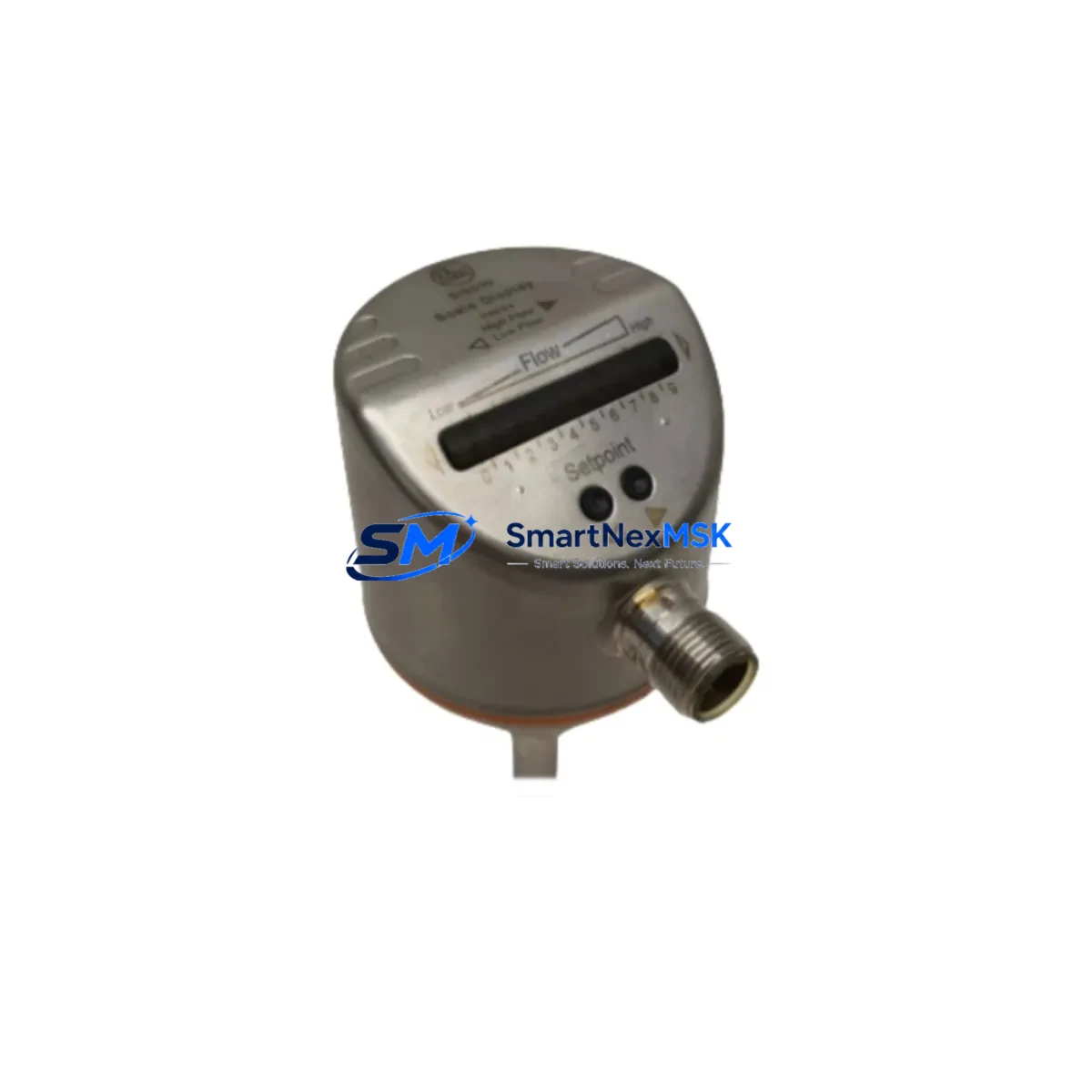
| Housing / Thread | M18 × 1, stainless steel, flush-mountable |
| Output Type | PNP, Normally Open (NO), 3-wire DC |
| Supply Voltage | 10–36 V DC |
| Sensing Range | 5 mm (standard) / 8 mm (extended flush) |
| Protection Rating | IP67 (IEC 60529) |
| Connector / Cable | M12 × 1 quick-disconnect, 4-pin A-coded |
| PLC Input Compatibility | Siemens S7-300/400/1200/1500, Allen-Bradley CompactLogix / MicroLogix, Mitsubishi FX / Q Series, Omron CJ/CS Series |
| Communication Protocol | Standard discrete I/O (24 V DC); IO-Link V1.1 capable variant available |
| Wiring Terminal Compatibility | Direct replacement on Phoenix Contact PTFIX and Weidmüller WDU terminal blocks |
| Commissioning Requirement | No program change required for direct replacement; address verification recommended |
| Warranty | 12 months from date of shipment |
Retrofit Planning for Existing Automation Systems
A successful SI5010 retrofit begins with a thorough audit of the existing control cabinet. Before removing the legacy sensor, technicians should document the terminal block wiring diagram, confirm the 24 V DC supply rail capacity on the power supply module — typically an IFM DN2031 or equivalent SITOP PSU100S — and verify that the digital input module’s sink/source configuration matches the PNP output of the SI5010. On Siemens S7-300 systems, the SM 321 DI 16×DC 24V input card accepts PNP signals natively; on Allen-Bradley CompactLogix platforms, the 1769-IQ16 input module requires no jumper changes for PNP-to-common wiring.
For installations using IO-Link communication, the SI5010 IO-Link variant connects to an IFM AL1350 or AL1352 IO-Link master, enabling parameterization via IODD descriptor files without modifying the upstream PROFINET or EtherNet/IP network topology. This is particularly valuable when migrating from older fieldbus architectures — such as AS-Interface or DeviceNet — where the IO-Link master acts as a transparent gateway, preserving the existing HMI tag structure on Siemens WinCC or Rockwell FactoryTalk View SE without screen redevelopment.
When the control cabinet houses a mixed rack — for example, a Siemens ET 200S distributed I/O station with a 4DI High Feature input module alongside an IFM CR0031 evaluation unit — the SI5010 can be wired in parallel to both systems during the transition period, allowing live signal comparison before the legacy sensor is decommissioned. Backplane slot addressing should be confirmed in the hardware configuration (HW Config in STEP 7 or TIA Portal Device View) to ensure the replacement sensor maps to the correct process image input (PII) byte. If the original sensor occupied a non-default address due to a previous rack expansion with additional IFM modules, the address must be re-verified before the first production cycle.
Cable management is a frequently overlooked retrofit variable. The SI5010 uses an M12 4-pin A-coded connector, compatible with standard IFM EVT001 and EVT002 sensor cables. If the existing installation uses a hardwired cable rather than a quick-disconnect, a field-wireable M12 connector such as the Belden 1200A or Phoenix Contact SACC-M12MS-4CON-PG9 can be crimped on-site, eliminating the need to re-route conduit. Confirm cable length against the maximum load current specification to avoid voltage drop at the input module threshold.
Downtime Control During System Migration
Minimizing production interruption during a sensor replacement requires a structured hot-swap protocol. Begin by placing the affected PLC input channel in force mode — using STEP 7 / TIA Portal’s “Force Table” or RSLogix 5000’s “Controller Tags” force function — to hold the last known good state of the input signal while the physical sensor is exchanged. This prevents nuisance faults from propagating to upstream interlocks or downstream conveyor sequences that depend on the sensor’s presence signal.
Once the SI5010 is mechanically installed and wired, release the force and perform a teach-in cycle if the application uses a switching distance adjustment. Confirm the LED indicator on the SI5010 switches correctly against the target material at the rated sensing distance. Log the commissioning result in the maintenance management system (CMMS) with the sensor serial number, installation date, and terminal reference for future traceability. The entire hot-swap procedure — from force activation to commissioning confirmation — typically completes within 15 to 25 minutes for a single sensor node, keeping unplanned downtime well within acceptable limits for most production schedules.
For multi-sensor replacement campaigns across an entire production line, a staged migration plan is recommended: replace sensors zone by zone during scheduled maintenance windows, validate each zone independently before advancing, and maintain a buffer stock of SI5010 units on-site to support immediate response to unplanned failures. All units shipped by SMARTNEXMSK are covered by a 12-month warranty and undergo pre-shipment functional testing to confirm output switching, supply current draw, and LED indication before dispatch.
Retrofit Support FAQ
Q1: Is the IFM SI5010 a direct drop-in replacement for the SI5000 and SI5001?
Yes. The SI5010 shares the same M18 thread pitch, PNP NO output configuration, M12 connector pinout, and 10–36 V DC supply range as the SI5000 and SI5001. No wiring changes or PLC program modifications are required for a direct substitution. Confirm the sensing range specification matches your application gap before installation.
Q2: Can the SI5010 be used with an IO-Link master for remote parameterization?
The IO-Link capable variant of the SI5010 is compatible with IFM AL1350, AL1352, and AL1900 IO-Link masters. The IODD file is available from IFM’s ifm.com product portal. Standard discrete-output variants operate as conventional 3-wire PNP sensors and do not require an IO-Link master.
Q3: What wiring checks are required before powering up the replacement sensor?
Verify BN (brown) = +24 V DC supply, BU (blue) = 0 V common, BK (black) = signal output to PLC input terminal. Confirm the PLC input module is configured for PNP (sourcing) input. Check terminal block torque to 0.5–0.6 Nm on Phoenix Contact or Weidmüller terminals. Measure supply voltage at the sensor connector before energizing to rule out wiring faults.
Q4: What does the 12-month warranty cover, and how is it claimed?
The 12-month warranty covers manufacturing defects, premature output failure, and housing integrity under normal operating conditions. It does not cover damage from incorrect wiring, overvoltage, or mechanical impact. To initiate a warranty claim, contact SMARTNEXMSK at sales@smartnexmsk.com with the order number, sensor serial number, and a description of the fault. Replacement units are dispatched within 3 business days of claim approval.
© 2026 SMARTNEXMSK. All rights reserved.
Original Source: https://smartnexmsk.com
Contact: sales@smartnexmsk.com | +86 18259474341