INERTIA DYNAMICS M1819-0002 Retrofit-Ready Fail-Safe Electromagnetic Brake: Compatible Modernization for Legacy Control Systems
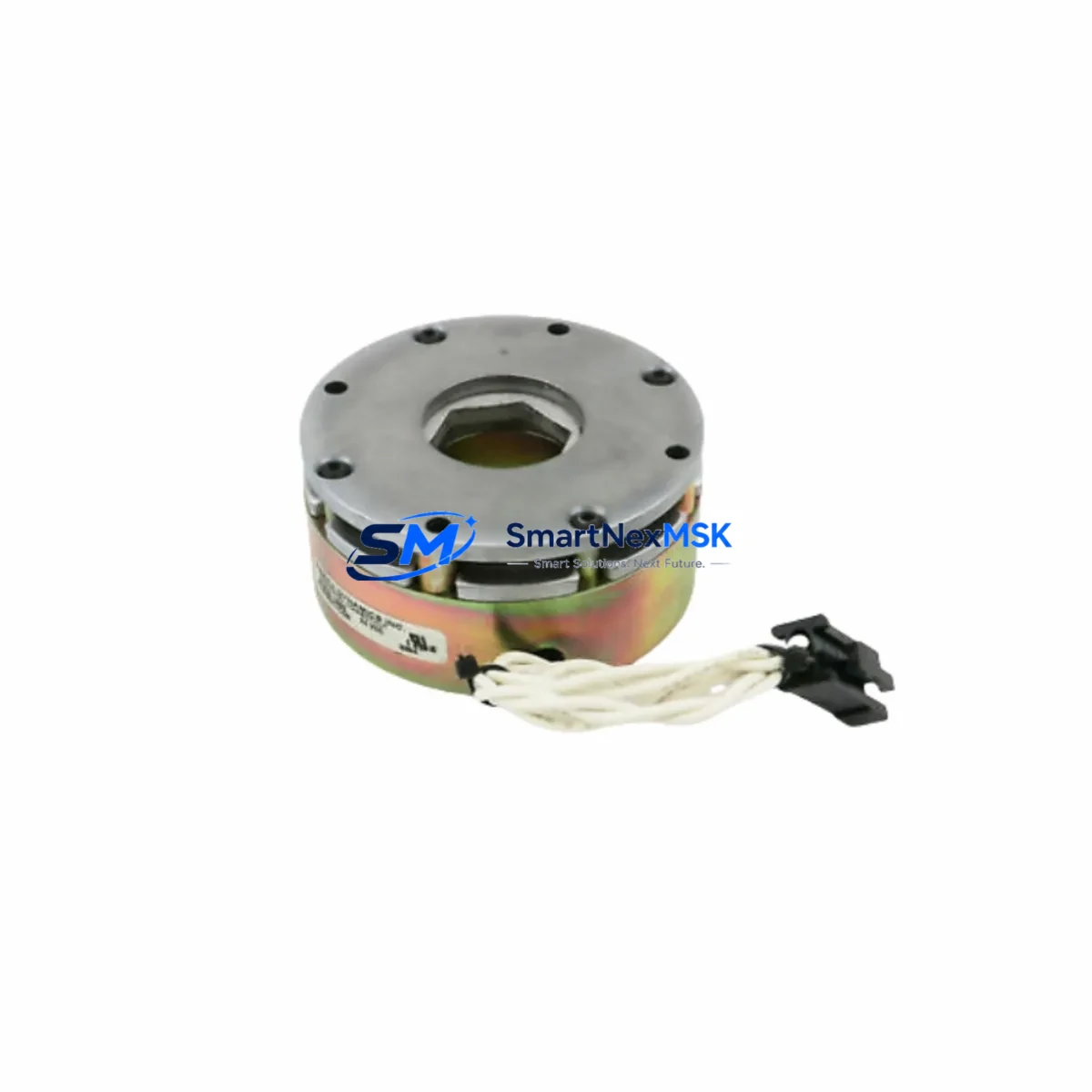
The INERTIA DYNAMICS M1819-0002 is a spring-applied, fail-safe electromagnetic micro brake engineered for demanding industrial motion control applications. Operating at 24VDC, this compact brake module delivers reliable holding torque and immediate engagement upon power loss — a critical safety characteristic for servo-driven axes, conveyor systems, rotary indexers, and automated assembly lines where uncontrolled motion is unacceptable.
As legacy automation platforms age and OEM spare parts become increasingly difficult to source, the M1819-0002 has emerged as a preferred retrofit and replacement solution for engineers managing aging motion control infrastructure. Whether you are replacing a worn-out brake on an existing servo axis, upgrading a discontinued brake module within a multi-axis control cabinet, or standardizing your spare parts inventory across a production facility, the M1819-0002 offers a dimensionally compatible, electrically equivalent path forward with minimal downtime.
This unit is fully tested prior to shipment, backed by a 12-month warranty, and available from verified stock — making it a dependable choice for both emergency replacement and planned maintenance programs.
Upgrade Compatibility Table
| Parameter | M1819-0002 Specification | Retrofit Notes |
|---|---|---|
| Supply Voltage | 24VDC | Verify drive output voltage matches; most modern servo drives supply 24VDC brake output natively |
| Brake Type | Spring-Applied, Fail-Safe | Engages on power loss — confirm replacement unit matches fail-safe logic of original design |
| Mounting Interface | Micro flange mount | Check shaft diameter and keyway dimensions against motor shaft before installation |
| Terminal Connection | Flying leads / connector | Match lead polarity; use shielded cable in high-EMI environments near VFDs or servo amplifiers |
| Communication Compatibility | N/A (hardwired brake) | Brake enable signal typically sourced from servo drive digital output or safety relay module |
| Replacement Recommendation | Direct drop-in for M1819-0002 and compatible legacy variants | Confirm torque rating matches application load inertia before commissioning |
| Commissioning Focus | Air gap adjustment, torque verification | Measure air gap per OEM spec; perform no-load and full-load brake test before returning to production |
| Warranty | 12 Months | Covers manufacturing defects; includes pre-shipment functional test report on request |
Retrofit Planning for Existing Automation Systems
Integrating the M1819-0002 into an existing automation system requires a structured approach that accounts for both mechanical and electrical compatibility across the control architecture. In most retrofit scenarios, the brake is mounted directly to the motor rear shaft and wired to the servo drive’s dedicated brake output circuit. Engineers should verify that the drive — whether a legacy unit or a modern replacement such as a current-generation servo amplifier — provides a 24VDC brake release signal with sufficient current capacity to energize the coil reliably.
Within the control cabinet, the brake circuit is typically supervised by a safety relay module or a PLC digital output card. When upgrading from an older control platform, it is common to encounter wiring routed through terminal blocks on a DIN-rail mounted distribution assembly. Careful labeling and continuity testing of each brake circuit conductor before and after the swap prevents miswiring that could result in unintended brake engagement or release during machine startup.
For systems where the M1819-0002 is installed on a servo motor paired with a multi-axis motion controller, the brake enable logic must be verified in the controller’s axis configuration parameters. Many motion controllers — including those using EtherCAT, PROFIBUS, or DeviceNet communication backbones — manage brake sequencing through dedicated function blocks that introduce a configurable delay between drive enable and brake release. This sequencing must be preserved during any hardware swap to prevent shaft shock or position loss at axis enable.
In applications involving a programmable logic controller managing the overall machine sequence, the brake interlock logic within the PLC program should be reviewed to confirm that the brake output address, safety interlock rungs, and fault reset routines remain valid after the hardware change. If the retrofit also involves replacing an aging I/O module or upgrading the rack backplane, engineers should audit all cross-references to the brake output coil address to ensure program integrity is maintained.
Where the system includes an HMI panel displaying axis status or brake state, the corresponding screen object tags should be verified against the updated I/O map. In older installations, brake status feedback may be wired through an auxiliary contact on the brake circuit back to a discrete input module, and this feedback path must be confirmed operational before the machine is returned to automatic mode.
For facilities managing a fleet of identical machines, standardizing on the M1819-0002 as the approved replacement brake simplifies spare parts management and reduces the risk of incorrect substitutions. Maintaining a small buffer stock of this module — alongside compatible servo drive brake output fuses, shielded brake cable assemblies, and terminal block connectors — supports rapid response to unplanned failures without extended production interruptions.
Downtime Control During System Migration
Minimizing unplanned downtime during a brake replacement or broader motion control retrofit requires preparation that begins well before the maintenance window opens. The first priority is to capture and back up the existing machine program, including all axis parameters, safety configurations, and HMI project files. For systems running on a PLC with a removable memory card or battery-backed RAM, a verified program backup eliminates the risk of configuration loss if the controller must be powered down during the brake swap.
Before removing the failed or obsolete brake, document the existing wiring connections with photographs and a written terminal map. Note the cable routing, strain relief positions, and any cable ties or conduit entries that will need to be replicated on the new unit. This documentation accelerates reinstallation and reduces the chance of wiring errors that could extend the outage.
During the physical swap, work methodically: isolate the brake circuit at the safety relay or drive output, discharge any residual voltage, remove the old brake, install the M1819-0002, and verify the air gap before reconnecting the wiring. Once the brake is mechanically secured and electrically connected, perform a controlled power-up sequence — energize the control circuit first, confirm the brake releases correctly at the drive enable signal, and then perform a low-speed jog test before returning the axis to full automatic operation.
For critical production lines where even a brief outage carries significant cost, consider pre-staging a fully wired and tested replacement assembly — motor, brake, and encoder — that can be swapped as a complete unit. This approach reduces in-situ work time to a mechanical exchange and cable reconnection, often cutting total downtime to under one hour even for complex multi-axis systems.
Throughout the migration, maintain clear communication with the production team regarding the expected timeline and any risks of extended outage. A structured commissioning checklist — covering brake torque verification, safety interlock confirmation, HMI status validation, and a supervised production trial run — ensures that the system is fully validated before the maintenance team stands down.
Retrofit Support FAQ
Q1: Is the M1819-0002 a direct replacement for the original INERTIA DYNAMICS brake on my servo motor?
In most cases, yes. The M1819-0002 is designed as a direct replacement for compatible INERTIA DYNAMICS micro brake variants sharing the same flange interface and 24VDC coil specification. Before ordering, confirm the shaft diameter, keyway dimensions, and required holding torque against your motor datasheet to ensure a precise mechanical and functional match.
Q2: What wiring checks should I perform before commissioning the replacement brake?
Verify that the brake supply voltage at the drive output or safety relay measures 24VDC ±10% under load. Check conductor polarity, confirm shielded cable is used if the run passes near VFD or servo drive power cables, and test continuity from the drive brake output terminal through to the brake coil leads. Measure coil resistance against the published specification to confirm the unit is intact before applying power.
Q3: Will I need to modify my PLC program or servo drive parameters after installing the M1819-0002?
Typically no program changes are required for a like-for-like brake replacement. However, if the retrofit is part of a broader system upgrade — such as replacing an I/O module, changing the drive model, or migrating to a new control platform — review the brake enable output address, brake sequencing delay parameters in the drive, and any safety interlock rungs in the PLC program that reference the brake circuit. Update and re-verify these elements before returning the machine to production.
Q4: What does the 12-month warranty cover, and is pre-shipment testing available?
The 12-month warranty covers manufacturing defects in materials and workmanship from the date of shipment. Each unit undergoes functional testing prior to dispatch to verify coil energization, mechanical engagement, and release performance. A pre-shipment test report is available on request. Warranty claims are supported by our technical team, and replacement units are dispatched promptly to minimize any impact on your production schedule.
© 2026 SMARTNEXMSK. All rights reserved.
Original Source: https://smartnexmsk.com
Contact: sales@smartnexmsk.com | +86 18259474341