INPUT 3402062000 Retrofit-Ready Digital Input for 640 Series Control Systems
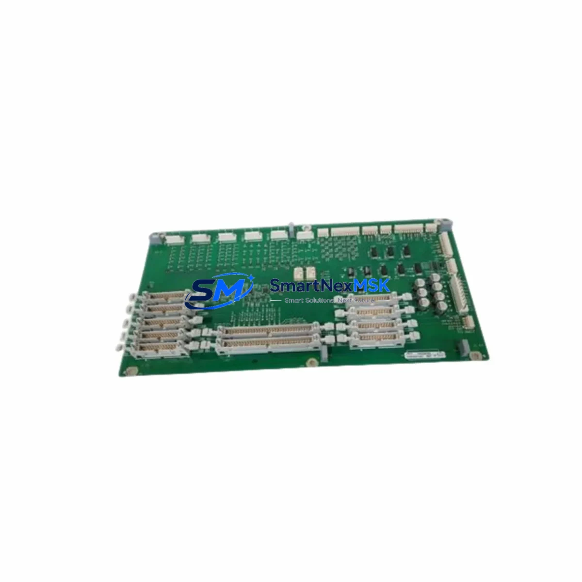
The INPUT 3402062000 (also catalogued as 640-34020619XD-1FA and 640-34020619XD-2FA) is a retrofit-ready digital input module engineered for seamless integration into 640 Series programmable logic controller platforms. Whether you are replacing a discontinued component on an aging production line, upgrading a legacy control cabinet, or restoring a system after an unplanned failure, this module delivers the electrical compatibility, signal integrity, and mechanical fit required to keep your automation infrastructure operational with minimal disruption.
Sourced directly from verified industrial supply channels and pre-tested prior to dispatch, each unit ships with a 12-month warranty covering manufacturing defects and functional failures under normal operating conditions. Our inventory is maintained to support urgent retrofit and emergency replacement scenarios, with same-day processing available for in-stock orders.
Upgrade Compatibility Table
| Parameter | Details |
|---|---|
| Primary SKU | 3402062000 |
| Alternate Part Numbers | 640-34020619XD-1FA / 640-34020619XD-2FA |
| Compatible Platform | 640 Series PLC Control Systems |
| Module Type | Digital Input (DI) |
| Installation Interface | 640 Series backplane / rack-mount slot |
| Terminal Wiring | Compatible with existing field wiring harness; no re-termination required in standard swap scenarios |
| Communication Compatibility | Native 640 Series I/O bus; compatible with existing CPU and communication modules |
| Replacement Recommendation | Direct drop-in for discontinued or failed 640-34020619XD variants |
| Commissioning Notes | Verify module address assignment in PLC configuration software before power-on; confirm I/O mapping in HMI tag database |
| Origin | China (CN) |
| Weight | 840 g |
| Warranty | 12 Months — covers manufacturing defects and functional failures under normal operating conditions |
Retrofit Planning for Existing Automation Systems
Successful integration of the INPUT 3402062000 into an existing 640 Series control system requires a structured pre-installation review. Before removing the failed or obsolete module, engineers should document the current slot address, I/O channel assignments, and any force-table entries active in the PLC program. The 640 Series rack architecture typically accommodates both local and remote I/O expansion, so confirming whether the module resides on the main rack or an extended I/O rack connected via a remote I/O adapter is an essential first step.
Power budget verification is critical when adding or replacing modules in a populated rack. The 640 Series power supply module — commonly a dedicated DC bus supply rated for the total I/O load — must have sufficient headroom to support the replacement digital input module without triggering an overload fault. If the existing power supply is already operating near capacity due to previously installed analog input modules, communication modules, or specialty function modules, a power audit should be completed before proceeding.
Terminal block wiring on the INPUT 3402062000 follows the standard 640 Series field wiring convention. In most retrofit scenarios, the existing wiring harness can be transferred directly to the replacement module without modification, provided the field device voltage levels and signal types remain unchanged. Engineers should inspect terminal screws for corrosion and verify torque specifications during reinstallation, particularly in high-vibration environments such as press lines or compressor control panels.
For systems that include a 640 Series CPU module managing multiple I/O drops, the module address must be confirmed in the PLC configuration file. If the replacement module is installed in the same physical slot as the original, the address assignment is typically preserved automatically. However, if the slot position has changed — for example, due to rack reconfiguration or the addition of a new specialty module — the address must be reassigned in the programming software and the project must be re-downloaded to the controller.
HMI screen updates are often overlooked during module replacements. If the control system includes an operator panel or SCADA interface referencing specific I/O tags mapped to the replaced module, the tag database should be audited to confirm that all display elements, alarm setpoints, and trend historians continue to reference valid addresses after the swap. This is especially relevant in systems where the HMI communicates with the PLC via an Ethernet communication module or a serial communication module using Modbus or proprietary protocols.
For larger retrofit projects involving multiple I/O modules, a phased replacement approach is recommended. Replacing the digital input module first — while leaving analog output modules, PID control modules, and high-speed counter modules in place — allows the control team to validate basic I/O functionality before committing to a full system upgrade. This approach also simplifies fault isolation if commissioning issues arise.
Programming cable compatibility should be confirmed before beginning any offline configuration work. The 640 Series programming port typically accepts a dedicated serial or USB programming cable, and the correct driver version must be installed on the engineering workstation to establish a reliable connection. Having a verified programming cable and a backup copy of the current PLC program on a secure storage device is a non-negotiable prerequisite for any retrofit operation.
Downtime Control During System Migration
Minimizing unplanned downtime is the primary operational concern when replacing a digital input module in a live production environment. The INPUT 3402062000 is designed to support hot-swap-compatible rack architectures where the 640 Series platform permits module replacement without a full system power-down, subject to the specific CPU firmware version and rack configuration in use. Engineers should consult the 640 Series hardware manual to confirm whether the installed CPU supports partial rack power cycling or online module replacement before attempting a live swap.
Where a controlled shutdown is required, the recommended procedure is to place the PLC in a safe stop state, force all output modules to a de-energized condition, and document the current program status — including any active timers, counters, and data registers — before removing the module. This preserves the control logic state and allows the system to resume from a known condition after the replacement module is installed and the program is restarted.
To protect original program logic during the migration, a full project backup should be exported from the programming software and stored on an isolated engineering workstation or secure network share before any hardware changes are made. If the retrofit involves a firmware update to the CPU module or communication module alongside the I/O replacement, the firmware upgrade should be performed and validated in a test environment before being applied to the production system.
Field control continuity can be maintained during brief outages by coordinating with the process control team to identify which field devices — sensors, limit switches, proximity detectors — are connected to the affected digital input channels, and temporarily routing critical signals through available spare channels on adjacent I/O modules if the process safety plan permits. This approach is particularly effective in systems with redundant I/O capacity or where the 640 Series rack includes unused input channels on neighboring modules.
Post-installation, a structured commissioning sequence should be followed: power on the rack, confirm the module status LED indicates normal operation, verify the I/O channel states in the PLC diagnostic display, and perform a point-to-point field device test for each input channel before returning the system to automatic mode. All commissioning results should be recorded in the site maintenance log to support future audits and warranty claims.
Retrofit Support FAQ
Q1: Is the INPUT 3402062000 a direct replacement for the 640-34020619XD-1FA and 640-34020619XD-2FA?
Yes. The 3402062000 is the current active part number covering both the -1FA and -2FA variants of the 640-34020619XD digital input module. It is designed as a direct functional and mechanical replacement for both discontinued variants within the 640 Series rack system.
Q2: Do I need to modify the PLC program after installing this module?
In most cases, no program modification is required if the module is installed in the same rack slot as the original. The I/O address mapping is preserved by the slot position. However, if the slot position changes, or if the CPU firmware version differs from the original configuration, a configuration update and program re-download may be necessary. Always verify I/O mapping in the PLC configuration software before returning the system to service.
Q3: What pre-shipment testing is performed on this module?
Each INPUT 3402062000 unit undergoes functional verification prior to dispatch, including power-on self-test, channel continuity checks, and communication bus response validation. Units that do not pass all test criteria are quarantined and not shipped. A test record is available upon request for quality-critical applications.
Q4: What does the 12-month warranty cover, and how is a warranty claim initiated?
The 12-month warranty covers manufacturing defects and functional failures occurring under normal operating conditions, including signal channel failures, communication bus faults, and power regulation issues attributable to the module itself. Physical damage caused by incorrect installation, overvoltage events, or environmental contamination is excluded. To initiate a warranty claim, contact our sales team with the order reference number, a description of the fault, and the site commissioning date. Replacement units are dispatched upon fault confirmation.
© 2026 SMARTNEXMSK. All rights reserved.
Original Source: https://smartnexmsk.com
Contact: sales@smartnexmsk.com | +86 18259474341