INTORQ BFK458-12E Maintenance-Ready Spare for BFK458 Automation
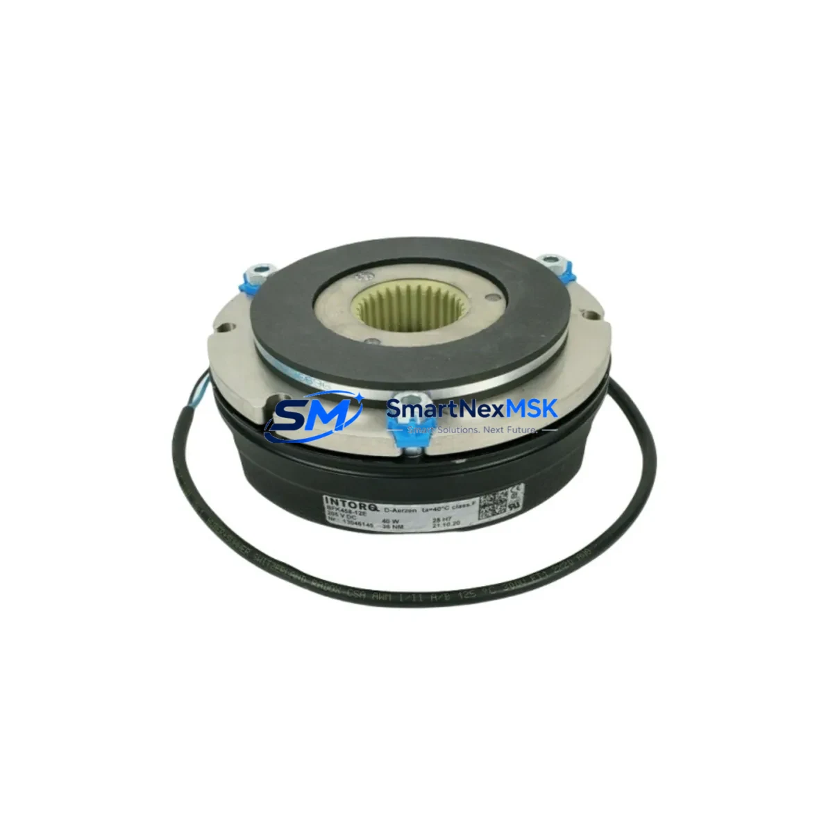
The INTORQ BFK458-12E is a spring-applied, fail-safe electromagnetic brake engineered for precision motion control in industrial automation systems. As a maintenance-ready spare, it is designed to support rapid field replacement, minimize unplanned downtime, and sustain the operational integrity of servo-driven axes, hoisting equipment, conveyor systems, and multi-axis CNC platforms. Every unit supplied by SMARTNEXMSK is sourced as an original INTORQ component, pre-shipment tested, and backed by a 12-month warranty — ensuring that your maintenance team receives a part that performs to OEM specification from day one.
For maintenance engineers managing aging automation infrastructure, the BFK458-12E represents a critical line-of-defense component. Fail-safe brakes are among the highest-consequence items in a control cabinet or drive train: a degraded or failed brake can result in uncontrolled axis movement, load drops, or safety interlock trips. Stocking a verified spare eliminates the lead-time risk associated with emergency procurement and allows planned replacement during scheduled maintenance windows rather than reactive repair under production pressure.
Procurement engineers sourcing for MRO inventories will find the BFK458-12E straightforward to qualify. The BFK458 series maintains dimensional and electrical compatibility across its size range, and the -12E designation confirms the coil voltage and torque class. Cross-referencing against your existing drive system documentation — particularly the servo amplifier’s brake output specifications — is recommended before installation to confirm coil voltage match and cable connector compatibility.
Spare Maintenance Table
| Parameter | Specification |
|---|---|
| SKU / Part Number | BFK458-12E |
| Brand | INTORQ (Kendrion Group) |
| Series | BFK458 Spring-Applied Electromagnetic Brake |
| Operating Principle | Spring-applied, electromagnetically released (fail-safe) |
| Nominal Coil Voltage | 24 V DC (rectified supply) |
| Brake Torque Class | 12 Nm (nominal static torque) |
| Mounting Interface | Flange-mount, IEC motor shaft compatible |
| Ingress Protection | IP54 (standard); IP65 available on request |
| Ambient Temperature | -10 °C to +40 °C (operating) |
| Country of Origin | Germany |
| Compatibility | BFK458 series servo motors, hoisting drives, CNC axes |
| Warranty | 12 Months — SMARTNEXMSK Quality Guarantee |
| Shipment Condition | Pre-shipment tested, OEM packaging |
| Lead Time | In-stock: ships within 2 business days |
Maintenance Planning for Continuous Operation
When scheduling replacement of the BFK458-12E, a disciplined maintenance engineer will treat the brake swap as an opportunity to inspect the entire brake circuit and adjacent drive components. The brake coil is powered through the servo amplifier’s dedicated brake output — typically a 24 V DC switched output rated at 1–2 A. Before installing the new BFK458-12E, verify that the brake rectifier module (if external) is functioning correctly and that the DC bus voltage is within tolerance. A faulty rectifier delivering ripple voltage to the coil will accelerate wear on the new brake and cause erratic release behavior.
Inspect the motor power cable and brake cable simultaneously. On INTORQ-equipped servo motors, the brake leads are often integrated into the motor feedback cable assembly or routed through a separate M23 or M17 connector. Damaged insulation or corroded pins at the connector are a common root cause of intermittent brake faults that are misdiagnosed as brake mechanical failure. Replacing the BFK458-12E without addressing a degraded cable will result in repeat failures.
The servo drive’s brake control parameters — including brake release delay, brake apply delay, and brake monitoring current threshold — should be verified against the BFK458-12E datasheet after installation. Drives from common platforms used alongside INTORQ brakes often store these as configurable parameters; incorrect delay settings can cause the motor to attempt torque production before the brake fully releases, generating overcurrent faults or mechanical shock on the drivetrain.
For control cabinet inspections conducted alongside this replacement, maintenance teams should also check the 24 V DC power supply module feeding the brake circuit. Voltage sag under load, caused by an aging PSU or undersized rail, is a frequent contributor to slow brake release and increased coil temperature. Terminal blocks on the brake circuit branch — particularly spring-clamp or screw-clamp types subject to vibration — should be re-torqued and inspected for oxidation. Fuse holders protecting the brake output should be verified for continuity and correct fuse rating.
In systems where the BFK458-12E is installed on a vertical axis or hoist application, the safety relay or safety PLC module governing the brake enable signal must be tested for correct response time after the brake replacement. Safety-rated brake monitoring relays — which measure coil current to confirm brake engagement and release — should be included in the inspection checklist. If the system uses a fieldbus-connected safety module (e.g., PROFIsafe over PROFINET), confirm that the brake status diagnostic signal is correctly mapped and that no latched faults remain in the safety controller after the replacement procedure.
For older systems approaching end-of-life, stocking a second BFK458-12E unit alongside related consumables — including brake air gap shims, coil connector seals, and motor shaft O-rings — is a practical strategy to extend system service life without committing to a full drive system upgrade.
Site Replacement Workflow
Step 1 — Isolation and Lockout: De-energize the servo drive and confirm zero-energy state on the motor and brake circuit. Apply LOTO (Lockout/Tagout) per site safety procedures. For vertical axes, mechanically secure the load before releasing the brake.
Step 2 — Brake Circuit Verification: Before removing the old BFK458-12E, measure coil resistance across the brake terminals. An open circuit or significantly out-of-spec resistance confirms coil failure. Record the value for maintenance logs. Check the brake cable connector for pin damage, corrosion, or moisture ingress.
Step 3 — Mechanical Removal: Remove the brake mounting bolts in the sequence specified in the INTORQ BFK458 installation manual. Note the air gap setting on the old unit using a feeler gauge — this provides a baseline for the new unit’s initial adjustment. Clean the motor flange mating surface.
Step 4 — New Unit Installation: Mount the replacement BFK458-12E, torque fasteners to specification, and set the air gap per the datasheet value for the -12E torque class. Reconnect the brake cable, ensuring correct polarity on the DC coil terminals. Do not reverse polarity — the coil is not polarity-sensitive on most variants, but the rectifier bridge (if integrated) may be.
Step 5 — Functional Test: Energize the brake circuit in isolation (without enabling the servo drive) and confirm audible and tactile brake release. Measure coil current and compare against the rated value. Re-enable the drive and perform a low-speed jog cycle to confirm smooth brake engagement and release without mechanical noise or axis position error.
Step 6 — Documentation: Record the replacement date, new unit serial number, air gap measurement, and coil current reading in the equipment maintenance log. Update the spare parts inventory to trigger reorder of a replacement BFK458-12E unit.
Spare Parts Support FAQ
Q1: Is the BFK458-12E a direct drop-in replacement for older BFK458 series brakes?
The BFK458 series maintains consistent flange dimensions and shaft bore options across production generations, making the BFK458-12E a reliable mechanical replacement for earlier -12E variants. However, coil voltage and connector type should always be verified against the installed motor’s nameplate and wiring diagram before installation, as regional variants may differ.
Q2: How does SMARTNEXMSK verify the BFK458-12E before shipment?
Each unit undergoes pre-shipment inspection including coil resistance measurement, insulation resistance check, and mechanical engagement verification. Units are shipped in original or equivalent protective packaging with a test record. The 12-month warranty covers defects in materials and workmanship under normal operating conditions.
Q3: What is the recommended spare parts stocking strategy for BFK458-12E in a multi-axis system?
For systems with three or more BFK458-equipped axes, maintaining one spare unit per four axes is a practical baseline. For critical production lines or vertical load applications, a 1:2 ratio (one spare per two axes) is recommended. Spare units should be stored in a dry, vibration-free environment within the temperature range specified in the datasheet.
Q4: Can SMARTNEXMSK support long-term supply of BFK458-12E for legacy systems?
Yes. SMARTNEXMSK maintains sourcing relationships for INTORQ BFK458 series components to support legacy system maintenance programs. For planned multi-year procurement, contact our sales team to discuss volume pricing, reserved stock agreements, and extended supply commitments aligned with your maintenance schedule.
© 2026 SMARTNEXMSK. All rights reserved.
Original Source: https://smartnexmsk.com
Contact: sales@smartnexmsk.com | +86 18259474341