INTORQ BFK458-16E Retrofit-Ready Electromagnetic Brake for BFK458 Control Systems
The INTORQ BFK458-16E is a spring-applied, fail-safe electromagnetic brake engineered for seamless retrofit integration into existing BFK458 Series drive and control systems. As legacy automation lines age and original components reach end-of-life, the BFK458-16E provides a verified drop-in replacement path that minimizes engineering rework, reduces commissioning time, and restores full braking performance without requiring mechanical redesign of the control cabinet or drive assembly.
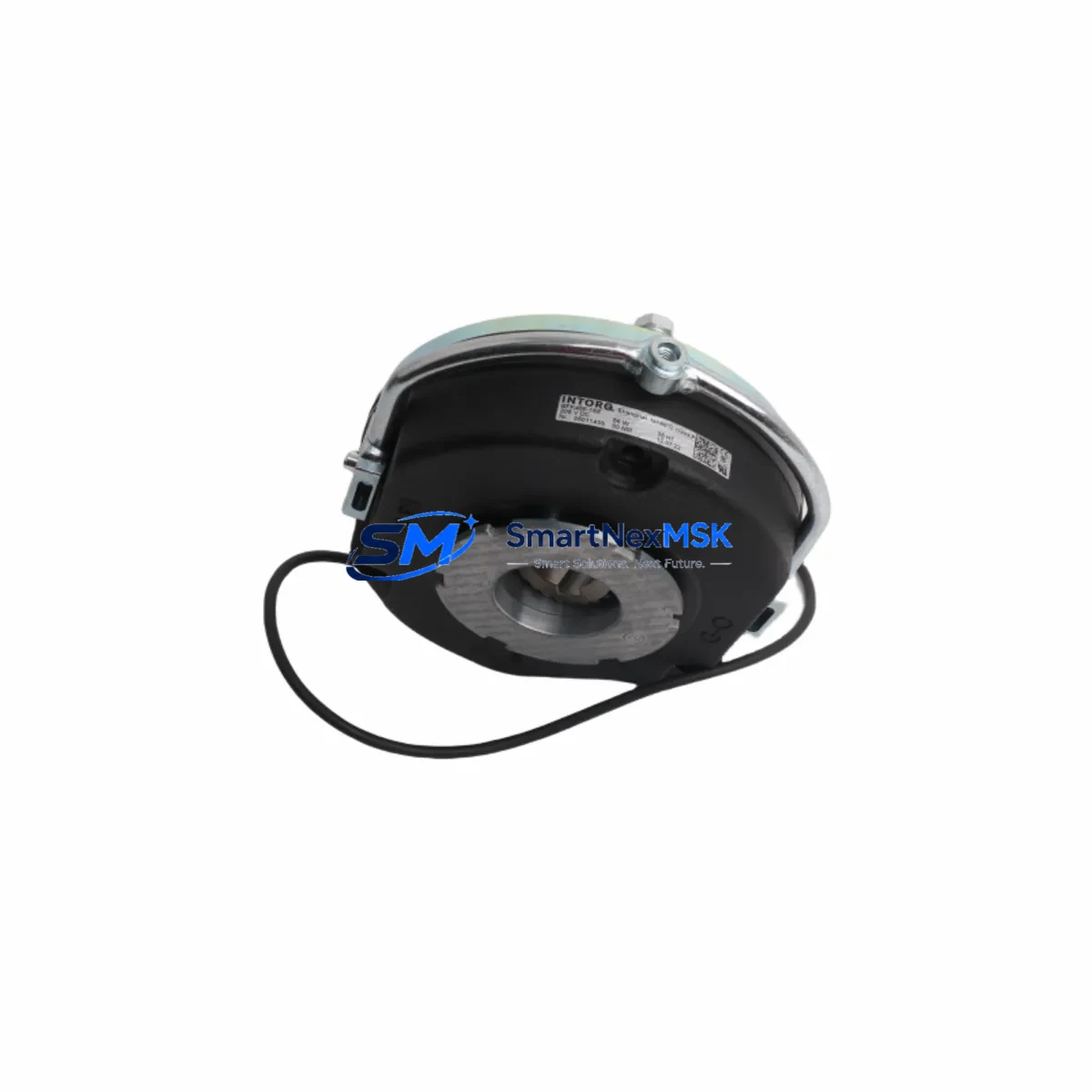
Designed and manufactured to INTORQ by Lenze’s exacting standards, the BFK458-16E maintains dimensional compatibility with the BFK458 Series mounting interface, preserving existing flange geometry, shaft bore tolerances, and terminal box orientation. This means that during a planned retrofit or emergency replacement, field engineers can swap the unit without modifying the motor adapter plate, backplate mounting pattern, or existing wiring harness — a critical advantage when downtime windows are measured in hours, not days.
Upgrade Compatibility Table
| Parameter | Detail |
|---|---|
| SKU / MPN | BFK458-16E |
| Series | INTORQ BFK458 |
| Brake Type | Spring-Applied Electromagnetic (Fail-Safe) |
| Mounting Interface | Compatible with BFK458 Series flange and shaft bore |
| Supply Voltage | 24 VDC / 205 VDC (rectified) — confirm with nameplate |
| Terminal Connection | Standard terminal box; matches BFK458 wiring layout |
| Communication / Control | Direct DC coil control; compatible with Lenze drive relay outputs and safety relay modules |
| Replacement Recommendation | Direct retrofit for BFK458-16 and BFK458-16E variants |
| Commissioning Notes | Verify air gap, coil resistance, and release voltage after installation |
| Warranty | 12 Months from shipment date |
Retrofit Planning for Existing Automation Systems
A successful BFK458-16E retrofit begins well before the unit arrives on-site. Engineers should start by auditing the existing control cabinet layout, confirming the DC power supply capacity — typically a 24 VDC regulated rail or a rectified AC supply via a Lenze EBR brake rectifier module — to ensure it can sustain the coil inrush current during engagement cycles without causing voltage sag on adjacent I/O cards.
The brake is typically controlled through a safety relay or a dedicated brake output on the Lenze 8400 series inverter or the i550 protec drive, both of which provide integrated brake management functions including release delay, holding current reduction, and fault monitoring. When migrating from an older Lenze 8200 vector drive, engineers should verify that the brake control output timing parameters are reconfigured in the new drive’s parameter set to match the BFK458-16E’s mechanical release time.
On the mechanical side, the existing motor adapter and flange plate should be inspected for wear before reuse. The BFK458-16E shares the same IEC frame interface as its predecessor, so in most cases the Lenze MF three-phase motor adapter remains serviceable. Terminal wiring from the brake rectifier to the terminal box should be checked for insulation integrity, particularly in environments with high vibration or thermal cycling, where cable fatigue is common near the conduit entry point.
For systems using a Lenze EASY Starter or Engineer software suite for parameterization, the brake control parameters can be pre-configured offline and downloaded via the standard USB or EtherCAT commissioning cable before the physical swap, further compressing the live commissioning window. HMI screens on connected Lenze p500 or third-party SCADA panels typically require no modification, as the brake status signal path through the drive’s digital output remains unchanged.
Where the retrofit involves I/O expansion — for example, adding a brake wear indicator contact or a thermal switch feedback loop — the Lenze I/O extension module or a dedicated terminal block assembly can be integrated into the existing DIN rail layout without requiring a new cabinet enclosure.
Downtime Control During System Migration
Minimizing production interruption during a BFK458-16E swap requires a structured pre-outage preparation protocol. Before the planned maintenance window, the replacement unit should be bench-tested: coil resistance measured, air gap set to the manufacturer’s specification, and manual release function verified. All terminal connections should be pre-labeled and the replacement wiring harness pre-assembled to match the existing layout.
During the outage, the drive should be placed in a safe torque off (STO) state and the brake supply isolated at the rectifier before disconnecting the terminal box. The original program logic in the Lenze controller should be backed up to a memory card or PC before any parameter changes are made, preserving the original control sequence as a fallback. After mechanical installation, the air gap should be re-verified with a feeler gauge, and the coil energized at reduced voltage to confirm smooth magnetic engagement before returning to full operating voltage.
Post-installation, a controlled test cycle — running the drive through its standard start-stop sequence at reduced load — confirms that brake release timing, holding torque, and fault response all meet the original system specification. This structured approach consistently achieves full system restoration within a single planned maintenance shift, protecting production continuity and avoiding unplanned extended outages.
Retrofit Support FAQ
Q: Is the BFK458-16E a direct replacement for the original BFK458-16?
A: Yes. The BFK458-16E is dimensionally and electrically compatible with the BFK458-16, sharing the same flange interface, shaft bore, and terminal box layout. Minor differences in coil resistance or release voltage should be confirmed against the original nameplate data before installation.
Q: What commissioning steps are required after installation?
A: After mechanical installation, verify the air gap using a feeler gauge per INTORQ specifications, measure coil resistance to confirm winding integrity, and perform a controlled energize/de-energize cycle to confirm smooth engagement. Drive brake control parameters should be reviewed and adjusted if migrating from a different drive generation.
Q: How is wiring compatibility confirmed before ordering?
A: Provide the original nameplate data (voltage, current, and brake type) and the existing drive model. Our technical team will confirm terminal compatibility and supply voltage requirements before shipment, ensuring a verified fit for your specific installation.
Q: What does the 12-month warranty cover?
A: The 12-month warranty covers manufacturing defects in materials and workmanship from the date of shipment. Each unit undergoes pre-shipment functional testing including coil resistance verification and mechanical release confirmation. Replacement or repair support is provided for any confirmed manufacturing defect within the warranty period.
© 2026 SMARTNEXMSK. All rights reserved.
Original Source: https://smartnexmsk.com
Contact: sales@smartnexmsk.com | +86 18259474341