JOPPICH TS-01 Retrofit-Ready Temperature Transmitter for Legacy Control Systems
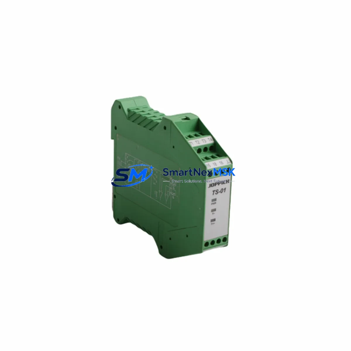
The JOPPICH TS-01 is a DIN rail-mounted temperature transmitter engineered for seamless integration into existing industrial control architectures. Designed with retrofit compatibility as a core requirement, the TS-01 accepts both RTD (Pt100, Pt1000) and thermocouple (Type K, J, T, E) inputs and delivers a standard 4–20 mA analog output — making it a direct functional replacement for discontinued transmitters commonly found in legacy ITS (Industrial Temperature Systems) control panels, distributed control system (DCS) analog input loops, and PLC-based process monitoring installations.
For facilities managing aging automation infrastructure, the TS-01 eliminates the need for full panel redesigns. Its compact 6 mm DIN rail footprint is compatible with standard 35 mm TS-35 mounting rails, and its screw-terminal wiring block accepts existing field cable gauges without re-termination. Engineers performing control cabinet upgrades can retain original wiring harnesses, reducing retrofit labor time and minimizing the risk of wiring errors during changeover.
Upgrade Compatibility Table
| Parameter | JOPPICH TS-01 | Typical Legacy Unit | Retrofit Notes |
|---|---|---|---|
| Sensor Input | RTD Pt100/Pt1000, TC Type K/J/T/E | RTD Pt100, TC Type K/J | Expanded input range; no sensor replacement required in most cases |
| Output Signal | 4–20 mA (2-wire) | 4–20 mA (2-wire) | Direct drop-in; no AI card reconfiguration needed |
| Supply Voltage | 10–30 VDC (loop-powered) | 12–28 VDC | Verify existing PSU output; most 24 VDC rails are compatible |
| DIN Rail Mounting | TS-35 (35 mm), 6 mm width | TS-35, 6–12 mm width | Check rail slot spacing in existing cabinet layout |
| Terminal Block | Screw terminals, 0.2–2.5 mm² | Screw terminals, 0.5–2.5 mm² | Existing field cables reusable without re-ferrule |
| Communication | Analog 4–20 mA (HART optional) | Analog 4–20 mA | Compatible with existing PLC analog input modules |
| Accuracy | ±0.1°C (RTD), ±0.5°C (TC) | ±0.2–0.5°C | Improved accuracy; HMI scaling may need minor adjustment |
| Operating Temp | -40°C to +85°C | -20°C to +70°C | Suitable for harsh environments without additional enclosure |
| Replacement Path | ITS legacy transmitters, generic DIN rail 4–20 mA units | — | Confirm module address and AI channel assignment in PLC program |
| Warranty | 12-Month Warranty — covers manufacturing defects; includes pre-shipment functional test report | ||
Retrofit Planning for Existing Automation Systems
A successful TS-01 retrofit begins with a thorough audit of the existing control cabinet. Before removing the legacy transmitter, engineers should document the current terminal wiring diagram, confirm the 24 VDC power supply rail capacity, and verify that the PLC analog input module — such as a Siemens SM 331 or equivalent AI card — is configured for 4–20 mA current input mode. If the existing system uses a Siemens S7-300 or S7-400 rack, the TS-01 output connects directly to the AI channel without any signal conditioning changes.
For installations built around older DCS platforms, such as Honeywell TDC 3000 or Yokogawa CENTUM CS 3000, the TS-01’s standard 4–20 mA output is natively compatible with field input cards. Engineers should confirm the field termination assembly (FTA) wiring and update the engineering unit scaling in the DCS configuration tool if the new transmitter’s calibrated range differs from the original unit.
In control panels where multiple temperature loops share a common power supply module — for example, a Phoenix Contact QUINT-PS or Weidmüller PRO MAX 24 VDC unit — verify that the total loop current budget accommodates the TS-01’s maximum consumption before commissioning. The TS-01 is loop-powered and draws no additional supply current beyond the 4–20 mA signal loop itself, which simplifies power budget calculations in dense multi-transmitter cabinets.
When the retrofit involves replacing transmitters connected to a Profibus PA or FOUNDATION Fieldbus segment, note that the TS-01 operates on a conventional 4–20 mA analog backbone. If the existing installation uses a Profibus PA coupler or FF linking device, the TS-01 can be wired to a conventional AI card on the same PLC rack, bypassing the fieldbus segment entirely — a common approach when fieldbus infrastructure is being decommissioned as part of a broader system modernization project.
For systems using a Mitsubishi MELSEC Q-series or iQ-R series PLC with analog input modules such as the Q64AD or R60AD4, the TS-01 integrates without firmware changes. Confirm the input range setting (4–20 mA mode) via GX Works3 or GX Works2 parameter configuration before powering the loop. Similarly, for Allen-Bradley ControlLogix or CompactLogix platforms with 1756-IF16 or 1769-IF4 analog input cards, the TS-01 wires directly to the field-side terminals with no additional signal conditioning required.
Backplane and rack considerations are minimal for the TS-01 since it is a field-mounted DIN rail device rather than a rack-inserted module. However, when planning the physical layout of the upgraded control cabinet, account for the TS-01’s 6 mm slot width and ensure adequate spacing from adjacent terminal blocks, circuit breakers, and power distribution components. Cable management should route sensor leads (RTD or thermocouple extension wire) separately from 24 VDC power conductors to minimize noise coupling on the low-level sensor signal.
Programming cable access is not required for the TS-01 itself, as configuration is performed via onboard DIP switches or a handheld calibrator. However, if the connected PLC program references the transmitter’s engineering unit range in a function block or structured text routine, update the scaling parameters in the PLC project file using the appropriate programming environment — Step 7, TIA Portal, Studio 5000, or GX Works — before going live. Retain a backup of the original program before making any modifications.
Downtime Control During System Migration
Minimizing production downtime during a temperature transmitter replacement requires a structured hot-swap procedure. Where process conditions permit, the TS-01 can be pre-wired and pre-configured on a temporary DIN rail segment outside the live cabinet, then swapped into the panel during a planned maintenance window. This approach reduces in-cabinet work time to under 15 minutes per transmitter position.
Before initiating the swap, place the affected PLC analog input channel in manual mode or force the process variable to a safe fallback value within the control program. This prevents the DCS or PLC from generating spurious alarms or triggering interlock logic during the brief period when the loop signal is interrupted. Document the forced value and restore automatic mode immediately after the new transmitter is confirmed online and reading correctly.
For multi-loop panels where several transmitters are being replaced in a single outage, sequence the work by process criticality — replace non-critical monitoring loops first to validate the procedure before moving to control-critical temperature loops. Use a portable loop calibrator to verify the TS-01’s 4 mA (0%) and 20 mA (100%) output endpoints against the expected engineering unit range before reconnecting to the PLC AI card.
HMI screen updates are typically not required if the replacement transmitter’s calibrated range matches the original unit. If the range has changed — for example, expanding from 0–200°C to 0–400°C — update the HMI tag scaling in the SCADA or HMI project (WinCC, FactoryTalk View, or equivalent) and verify that trend displays, alarm setpoints, and report templates reflect the new range before returning the loop to automatic control. All TS-01 units shipped by SMARTNEXMSK include a pre-shipment functional test report confirming output linearity and sensor input accuracy, supporting rapid commissioning and reducing field verification time.
Retrofit Support FAQ
Q1: Is the JOPPICH TS-01 a direct replacement for my existing ITS DIN rail temperature transmitter?
In most cases, yes. The TS-01 shares the same 4–20 mA output signal, 24 VDC loop power, and TS-35 DIN rail mounting as the majority of legacy ITS transmitters. Confirm your existing unit’s sensor input type (RTD or thermocouple) and wiring polarity before installation. No PLC program changes are required if the engineering unit range is unchanged.
Q2: What commissioning steps are required after installing the TS-01?
After wiring, apply loop power and verify the output current at 0% and 100% of the configured range using a loop calibrator or the PLC’s AI diagnostic function. Check that the PLC or DCS is reading the correct process value in engineering units. If the HMI displays an unexpected value, verify the AI channel scaling parameters in the PLC configuration. The TS-01 ships pre-calibrated and does not require field calibration under normal installation conditions.
Q3: Can the TS-01 be used in a system that previously used Profibus PA or HART transmitters?
The TS-01 outputs a standard 4–20 mA analog signal. It can replace a HART transmitter on a conventional 4–20 mA loop without any infrastructure changes — the HART communication layer is simply unused. Replacing a Profibus PA device requires connecting the TS-01 to a conventional analog input card rather than the PA segment; consult your PLC or DCS documentation for the appropriate AI card and wiring configuration.
Q4: What does the 12-month warranty cover, and what documentation is included?
The 12-month warranty covers manufacturing defects in materials and workmanship from the date of shipment. Each unit is shipped with a pre-shipment functional test report confirming sensor input accuracy and 4–20 mA output linearity. In the event of a warranty claim, contact sales@smartnexmsk.com with the order reference and test report. Replacement units are dispatched within 3 business days of claim confirmation.
© 2026 SMARTNEXMSK. All rights reserved.
Original Source: https://smartnexmsk.com
Contact: sales@smartnexmsk.com | +86 18259474341