KARL 52004-1.030 Retrofit-Ready Fan Module for DNG 3-6/TS Control Systems
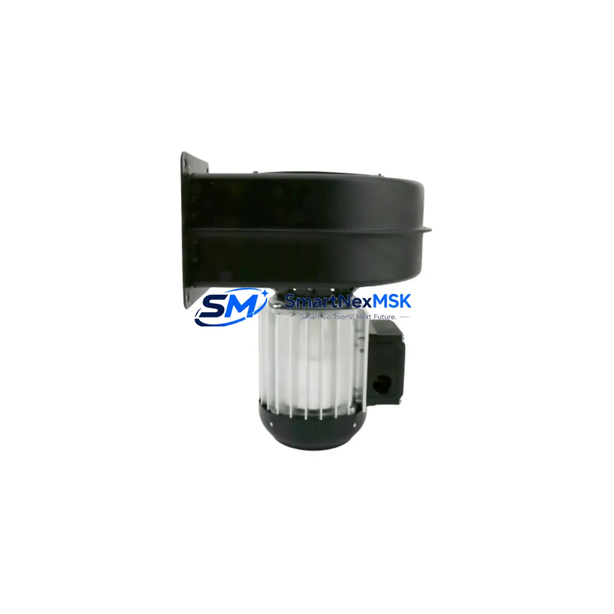
The KARL 52004-1.030 DNG 3-6/TS Fan Module (cross-reference: WS 0130-76142, DIP180, 0100-76142, W/ 0020-78718, 0100-77040) is a precision-engineered cooling component designed for seamless retrofit integration into legacy DNG 3-6/TS series control cabinets and automation enclosures. As original KARL fan modules reach end-of-life or become increasingly difficult to source, this retrofit-ready replacement provides a validated, drop-in solution that preserves thermal management performance without requiring structural modifications to the control cabinet or changes to the existing wiring harness.
Industrial facilities operating aging DNG 3-6/TS control systems face a critical challenge: maintaining thermal stability within the control enclosure while managing the transition away from discontinued OEM components. Overheating remains one of the leading causes of unplanned downtime in legacy PLC and DCS environments. The KARL 52004-1.030 addresses this directly by delivering equivalent airflow capacity, matching mounting dimensions, and compatible connector pinout — enabling maintenance teams to execute a controlled replacement during scheduled maintenance windows rather than emergency shutdowns.
Before proceeding with installation, engineers should verify the following parameters against the existing system documentation: supply voltage (typically 24 VDC or 115/230 VAC depending on cabinet configuration), rated airflow (m³/h), connector type and pin assignment, mounting orientation (horizontal or vertical airflow path), and any interlocked fan-fault signals wired into the PLC I/O rack. In systems where the fan-fault output is monitored by the controller — for example, through a digital input module on the same backplane — the replacement module must replicate the fault relay or open-collector signal to avoid spurious fault alarms in the SCADA or HMI display.
Upgrade Compatibility Table
| Parameter | Details |
|---|---|
| SKU / Part Number | 52004-1.030 DNG 3-6/TS |
| Cross-Reference | WS 0130-76142 / DIP180 / 0100-76142 / 0020-78718 / 0100-77040 |
| Brand | KARL |
| Product Type | Fan Module (Control Cabinet Cooling) |
| Compatible Series | DNG 3-6/TS Control Systems |
| Mounting Interface | Direct backplane / panel mount — matches OEM footprint |
| Communication Compatibility | Passive thermal component; no protocol dependency |
| Replacement Recommendation | Direct drop-in for discontinued 52004-1.030 OEM units |
| Commissioning Notes | Verify fan-fault signal wiring; confirm airflow direction before power-on |
| Origin | China (CN) |
| Warranty | 12 Months from date of shipment |
Retrofit Planning for Existing Automation Systems
A successful retrofit of the KARL 52004-1.030 fan module begins well before the physical swap. Maintenance engineers should pull the existing cabinet layout drawing and confirm the fan module’s position relative to the power supply module, CPU rack, and I/O expansion backplane. In DNG 3-6/TS installations, the fan module is typically positioned at the top or bottom of the enclosure to create a defined airflow path across heat-generating components including the main controller board, communication processor, and analog I/O modules.
When planning the retrofit, the following components commonly appear in the same control cabinet or upgrade scope and should be assessed simultaneously:
- The DNG 3-6/TS power supply module — confirm output voltage stability and load capacity before and after fan replacement, as thermal derating may affect PSU output under high ambient conditions.
- Digital input and output modules mounted on the same backplane — inspect terminal block condition and verify that no wiring has been routed across the fan module’s airflow path.
- The CPU or controller module within the DNG 3-6/TS rack — check firmware version compatibility if the fan-fault signal is processed by the controller’s diagnostic routine.
- Communication interface modules (e.g., PROFIBUS DP, Modbus RTU, or Ethernet/IP adapters) — these are sensitive to thermal excursions and benefit directly from restored cooling performance.
- Analog I/O modules — signal drift caused by elevated enclosure temperatures is a known failure mode; restoring proper airflow often resolves intermittent analog measurement errors without further hardware changes.
- The backplane or rack assembly itself — inspect for corrosion, loose module retention clips, or damaged guide rails that may have contributed to the original fan module failure.
- HMI panel or operator terminal connected to the DNG 3-6/TS system — after fan replacement, verify that any temperature-related alarm pages or fan-status indicators on the HMI display are cleared and functioning correctly.
- Programming cable and engineering workstation connection — have the programming interface ready (e.g., serial or USB-to-RS232 adapter) to perform a live diagnostic read of the controller after power restoration, confirming no fault codes remain active.
Terminal wiring should be photographed and documented before disconnecting any connectors. Label all cables with their originating terminal numbers. If the existing fan module uses a Molex, JST, or proprietary KARL connector, confirm the mating connector type on the replacement unit before ordering to avoid on-site delays.
Downtime Control During System Migration
Minimizing production downtime during a fan module replacement requires a structured approach. The KARL 52004-1.030 is designed for hot-swap-compatible enclosures where the control system can remain energized during the physical swap — however, this must be confirmed against the specific cabinet design and local safety regulations before proceeding.
Recommended procedure for downtime control:
- Pre-shutdown backup: Use the engineering workstation to perform a full program upload from the DNG 3-6/TS controller. Save the project file with a timestamped filename. This protects the control logic in the event of an unexpected power interruption during the swap.
- Controlled shutdown sequence: Follow the documented shutdown procedure for the DNG 3-6/TS system — typically placing the controller in STOP mode, disabling outputs, and then removing power from the cabinet in the correct sequence to avoid voltage spikes on sensitive modules.
- Physical replacement: Remove the failed 52004-1.030 fan module by releasing the retention mechanism, disconnecting the power connector, and sliding the module clear of its mounting position. Install the replacement unit, reconnect the power connector, and verify secure seating.
- Power restoration and verification: Restore cabinet power in reverse sequence. Monitor the HMI or engineering software for fan-fault alarms. Confirm airflow is present by checking for air movement at the exhaust vents. Allow the cabinet to reach thermal equilibrium (typically 10–15 minutes) before returning the controller to RUN mode.
- Program integrity check: After returning to RUN mode, verify that all I/O modules are communicating correctly, analog signal values are within expected ranges, and no diagnostic fault codes are active in the controller’s fault log.
For systems where any downtime is unacceptable, consider pre-staging the replacement fan module and all required tools at the cabinet location during a prior shift, so the actual swap can be completed within a single planned maintenance window of 15–30 minutes.
Retrofit Support FAQ
Q1: Is the KARL 52004-1.030 DNG 3-6/TS a direct replacement for the original OEM fan module?
Yes. The 52004-1.030 is supplied as a form-fit-function replacement for the original KARL DNG 3-6/TS fan module. Mounting dimensions, connector pinout, and airflow specifications match the OEM unit. Cross-reference part numbers WS 0130-76142, DIP180, 0100-76142, 0020-78718, and 0100-77040 are all covered by this SKU.
Q2: What commissioning steps are required after installation?
After physical installation, restore cabinet power and confirm the fan-fault signal (if wired to the PLC I/O) is not asserting a fault condition. Check the HMI for any active alarms related to cabinet temperature or fan status. Perform a full I/O check to confirm all modules are communicating correctly. No firmware changes or address reconfiguration are required for the fan module itself.
Q3: How is the unit tested before shipment?
Each KARL 52004-1.030 fan module undergoes functional testing prior to shipment, including motor run-in, airflow verification, and connector integrity check. Units are shipped in anti-static protective packaging with individual test records available upon request.
Q4: What does the 12-month warranty cover?
The 12-month warranty covers manufacturing defects, motor bearing failure, and connector faults under normal operating conditions. Warranty claims are supported by SMARTNEXMSK with replacement or repair at no additional cost. The warranty period begins from the date of shipment as confirmed by the shipping document.
© 2026 SMARTNEXMSK. All rights reserved.
Original Source: https://smartnexmsk.com
Contact: sales@smartnexmsk.com | +86 18259474341