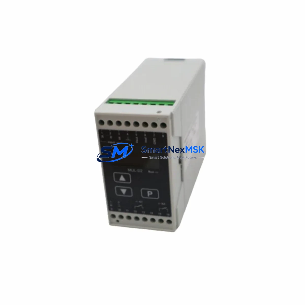
KFG LEVEL MUL-D2 Retrofit-Ready Potentiometric Transducer: Compatible Modernization for Legacy Control Systems
The KFG LEVEL MUL-D2 is a retrofit-ready potentiometric level transducer engineered to serve as a verified drop-in replacement for discontinued and aging KFG LEVEL Series instrumentation. Designed for industrial automation environments where system continuity, signal accuracy, and minimal downtime are non-negotiable, the MUL-D2 addresses the full spectrum of challenges encountered during legacy system modernization — from terminal rewiring and power supply verification to communication link re-establishment and HMI screen reconfiguration.
Whether you are managing a planned control cabinet upgrade, responding to an unexpected component failure, or executing a phased migration from an obsolete measurement platform, the MUL-D2 provides the mechanical compatibility, electrical specification alignment, and signal output consistency required to restore or enhance your process control loop without redesigning the surrounding infrastructure.
Upgrade Compatibility Table
| Parameter | Legacy KFG LEVEL Series | MUL-D2 Replacement | Retrofit Notes |
|---|---|---|---|
| Measurement Principle | Potentiometric / Resistive | Potentiometric | Direct signal-type compatibility; no transmitter reconfiguration required |
| Output Signal | Resistive / 0–10V / 4–20mA (model-dependent) | Resistive / 4–20mA | Verify AI module input type at PLC or DCS terminal block before wiring |
| Power Supply | 12–30 VDC | 12–30 VDC | Confirm existing PSU capacity; check rail loading if sharing with other field devices |
| Terminal Connection | 2-wire / 3-wire (model-dependent) | 2-wire / 3-wire | Match wiring diagram to existing terminal block layout; label conductors before disconnection |
| Mounting Interface | Threaded / Flanged process connection | Threaded / Flanged | Confirm process connection size and thread standard (G, NPT, or flange PN rating) |
| Communication Protocol | Analog (passive) | Analog (passive) | No protocol migration required; compatible with existing analog input cards |
| PLC/DCS Compatibility | Universal analog input | Universal analog input | Compatible with Siemens S7, Allen-Bradley ControlLogix, Schneider Modicon, and equivalent AI modules |
| HMI Tag Reconfiguration | Required if tag address changes | Retain existing tag if address unchanged | Verify PLC program scaling block; update engineering units if span differs |
| Commissioning Requirement | Full loop calibration | Loop calibration recommended | Perform zero/span calibration at process conditions; document as-found and as-left values |
| Warranty | Varies (legacy, often expired) | 12-Month Warranty | Covered from date of shipment; includes functional verification and outgoing test report |
Retrofit Planning for Existing Automation Systems
Successful integration of the MUL-D2 into an existing automation architecture begins well before the physical swap. Engineers and maintenance teams should conduct a pre-retrofit audit covering the following areas:
Power Supply Verification: Confirm that the existing 24 VDC power supply module — such as a Siemens SITOP PSU100S or equivalent rail-mount PSU — has sufficient residual capacity to support the MUL-D2 alongside other field devices sharing the same distribution rail. Overloaded power rails are a common root cause of intermittent signal faults after replacement.
Terminal Block and Wiring Adaptation: Before disconnecting the legacy transducer, photograph and document the existing terminal block layout. The MUL-D2 uses standard screw-terminal or spring-clamp connections compatible with DIN rail-mounted terminal blocks such as Phoenix Contact PTFIX or Weidmüller WDU series. If the original wiring used shielded cable, maintain shield continuity and ground at one end only to prevent ground loops.
Analog Input Module Compatibility: The MUL-D2 output is compatible with standard analog input modules across major PLC and DCS platforms. When replacing a sensor connected to a Siemens ET 200SP AI module, a Rockwell 1756-IF16 ControlLogix analog input card, or a Schneider Modicon STB AVI 1255 distributed I/O module, no hardware changes to the input card are required provided the signal type (4–20mA or resistive) matches. Verify the channel configuration in the PLC program and confirm that the input range scaling block reflects the MUL-D2 measurement span.
Backplane and Rack Considerations: In rack-based DCS architectures — such as those using Honeywell HC900 or Yokogawa CENTUM VP field control stations — the analog input card occupying the relevant backplane slot should be verified for signal type compatibility. No backplane modifications are required for passive analog replacement, but slot addressing must be confirmed in the controller configuration tool.
PLC Program and Function Block Review: Open the existing PLC project in the engineering workstation (e.g., Siemens TIA Portal, Rockwell Studio 5000, or Schneider EcoStruxure Control Expert) and locate the analog input function block associated with the level measurement loop. Verify the scaling parameters — raw input range, engineering unit range, and alarm setpoints — against the MUL-D2 datasheet. If the measurement span differs from the legacy device, update the scaling block before going live.
HMI Screen and Tag Validation: On the SCADA or HMI platform (Siemens WinCC, Rockwell FactoryTalk View, or Schneider Vijeo Designer), confirm that the level tag linked to this measurement point retains its address and data type. If the PLC tag address is unchanged, no HMI modification is required. If the tag was renamed or the I/O address shifted during the replacement, update the HMI tag database and perform a full screen simulation before returning the loop to automatic control.
Communication Link Integrity: For systems where the analog signal is transmitted over a HART-enabled loop or where the field device communicates via a HART multiplexer to an asset management system such as Emerson AMS Device Manager, confirm that the MUL-D2 HART revision is compatible with the host system. For purely passive analog loops, no communication configuration is required.
Field Calibration and Loop Test: After physical installation, perform a full loop calibration using a calibrator such as a Fluke 725 or equivalent. Apply simulated process levels at 0%, 25%, 50%, 75%, and 100% of span and verify that the PLC analog input reads within the specified accuracy band. Document calibration results and retain for maintenance records.
Downtime Control During System Migration
Minimizing process interruption during a level transducer replacement requires a structured approach to pre-staging, isolation, and restoration. The following practices are recommended for MUL-D2 retrofit projects:
Pre-Stage and Bench Test: Before the maintenance window, bench-test the MUL-D2 using a bench power supply and a calibrator to confirm output linearity across the full measurement span. This eliminates the risk of discovering a defective unit after the process has been isolated.
Program Backup: Export a full backup of the PLC project from the engineering workstation before any field changes. Store the backup on a network drive and a local USB drive. If the replacement requires any program modification, create a new program version rather than overwriting the production version.
Isolate Without Losing Loop Context: Place the affected control loop in manual mode at the PLC or DCS before isolating the field device. This preserves the last known output to the final control element (e.g., a control valve or pump) and prevents process upsets caused by a loss of measurement signal during the swap.
Parallel Verification: Where process conditions permit, temporarily connect the MUL-D2 in parallel with the legacy device before full cutover. Compare readings at the PLC analog input to confirm signal agreement before committing to the replacement.
Restore and Monitor: After installation and loop calibration, return the control loop to automatic mode and monitor the process variable trend for a minimum of 15 minutes to confirm stable, noise-free signal behavior. Check for ground loop interference, which may manifest as a fixed offset or periodic noise on the analog input.
The MUL-D2 is shipped with an outgoing functional test report confirming signal output accuracy. All units carry a 12-month warranty from the date of shipment, covering manufacturing defects and functional failures under normal operating conditions.
Retrofit Support FAQ
Q1: Is the MUL-D2 a direct drop-in replacement for all KFG LEVEL Series potentiometric transducers?
The MUL-D2 is designed as a functional replacement for KFG LEVEL Series potentiometric level transducers sharing the same process connection standard, signal output type, and power supply range. Before installation, confirm the process connection size, thread standard, measurement span, and output signal type against the MUL-D2 datasheet. Minor wiring adaptation may be required if the original unit used a non-standard terminal configuration.
Q2: What commissioning steps are required after installation?
After mechanical installation and terminal wiring, perform a full loop calibration at process conditions. Verify PLC analog input scaling, confirm HMI tag values match the calibrated output, and check for signal noise or ground loop artifacts. Document as-found and as-left calibration values. For HART-enabled loops, perform a HART communication check using a handheld communicator such as a Emerson 475 Field Communicator.
Q3: What does the 12-month warranty cover?
The 12-month warranty covers manufacturing defects and functional failures under normal operating conditions from the date of shipment. Each unit is shipped with an outgoing functional test report. Warranty claims require return of the defective unit with a description of the failure mode. Damage caused by incorrect wiring, overvoltage, or installation outside the specified environmental ratings is excluded.
Q4: Can the MUL-D2 be used with third-party PLC and DCS platforms?
Yes. The MUL-D2 produces a standard analog output (resistive or 4–20mA) compatible with any analog input module that accepts the corresponding signal type. It has been verified for use with Siemens S7-300/400/1500 series AI modules, Rockwell Automation 1756 and 1769 series analog input cards, Schneider Modicon M340 and M580 analog input modules, and equivalent distributed I/O systems. No special driver or configuration file is required.
© 2026 SMARTNEXMSK. All rights reserved.
Original Source: https://smartnexmsk.com
Contact: sales@smartnexmsk.com | +86 18259474341