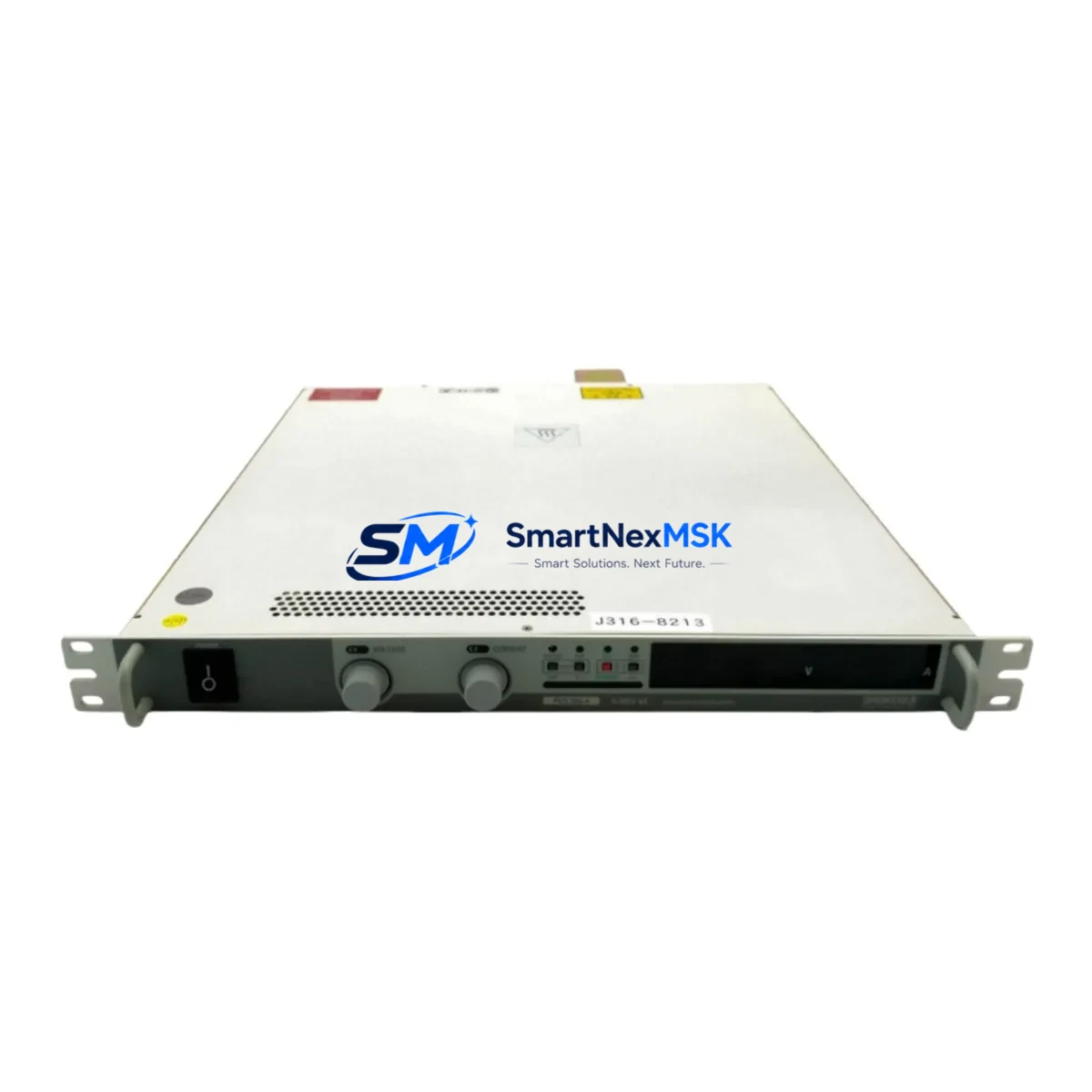
Kikusui PVS300-4 Retrofit-Ready DC Power Supply for PVS Series Control Systems
The Kikusui PVS300-4 (SKU: 0-300V 4A PVS300-4 VT3-V10D PC 300 17-157996-00) is a high-precision programmable DC power supply engineered for seamless integration into existing PVS Series test and automation platforms. With a rated output of 0–300 V / 0–4 A / 1200 W, this unit is purpose-built to serve as a drop-in retrofit replacement for aging or discontinued PVS Series supplies in industrial control cabinets, automated test equipment (ATE) racks, and laboratory power distribution systems. Whether you are upgrading a legacy bench setup, replacing a failed unit in a production line, or migrating from an older Kikusui PVS model, the PVS300-4 delivers the electrical compatibility, communication protocol support, and mechanical form factor required for a low-disruption changeover.
Upgrade Compatibility Table
| Parameter | PVS300-4 (This Unit) | Retrofit Notes |
|---|---|---|
| Output Voltage Range | 0 – 300 V DC | Matches PVS Series voltage envelope; verify load wiring insulation rating |
| Output Current Range | 0 – 4 A | Confirm upstream fuse and cable gauge (≥ 1.5 mm² recommended) |
| Rated Power | 1200 W | Verify cabinet PDU capacity before installation |
| Interface / Communication | RS-232C / GP-IB (IEEE-488) / USB (model-dependent) | Confirm interface card fitted; legacy GP-IB controllers remain compatible |
| Mounting Form Factor | Rack-mount / Bench (standard PVS chassis) | Direct rack-slot replacement for prior PVS300 variants |
| Programming Compatibility | SCPI command set | Existing SCPI sequences require no modification in most cases |
| Replacement Models | PVS300-4, supersedes earlier PVS300 revisions | Cross-reference part number 17-157996-00 for exact match |
| Commissioning Requirement | Output calibration check recommended post-installation | Use Kikusui calibration software or SCPI CAL commands |
| Warranty | 12 Months | Covers manufacturing defects; functional test report available on request |
Retrofit Planning for Existing Automation Systems
Successful integration of the PVS300-4 into a running production or test environment requires a structured pre-installation review. Begin by auditing the existing power distribution panel to confirm that the AC input branch circuit supplying the old supply can sustain the 1200 W draw of the replacement unit. In multi-supply racks where several Kikusui PVS600-2 or PVS1200-2 units share a common bus bar, recalculate total load before energising the new module.
Terminal wiring is the next critical checkpoint. The PVS300-4 uses standard 4 mm² binding post outputs; if the legacy installation used spade lugs or ring terminals sized for an older PVS250 or PVS500 variant, prepare the appropriate adapters in advance. Label all conductors before disconnection to prevent polarity reversal during reconnection — a common cause of load damage during rushed retrofits.
For systems controlled via GP-IB (IEEE-488), verify that the GPIB address set on the rear panel DIP switches of the PVS300-4 matches the address previously assigned to the retired unit. Controllers running LabVIEW, MATLAB Instrument Control Toolbox, or custom SCPI drivers will resume communication without code changes once the address is confirmed. If the host PC communicates via USB-TMC, install the Kikusui virtual COM port driver before the first power-on.
In ATE racks that also house a Kikusui PLZ series electronic load, a Kikusui PWR multi-output supply, or a third-party signal generator, confirm that the SCPI bus arbitration sequence in the test executive software correctly re-enumerates the new instrument. Systems using a Kikusui KFM2150 frequency analyser or a Kikusui PCR-LE AC power source on the same GPIB chain should be powered down sequentially to avoid bus contention during the swap.
Where the PVS300-4 feeds a DUT (device under test) through a switching matrix or relay board, inspect the relay contact ratings to ensure they are rated for 300 V DC at the expected current. Relay boards designed for earlier 150 V PVS variants may require replacement with higher-rated components such as those found in Omron G6K or Panasonic TQ series relay modules commonly used in industrial ATE fixtures.
Finally, update the asset register and calibration schedule to reflect the new serial number and the 12-month warranty start date. Retain the original functional test report supplied with the unit as evidence of pre-shipment verification.
Downtime Control During System Migration
Minimising production downtime during a power supply changeover begins with parallel preparation. Before taking the legacy unit offline, capture a full screenshot or export of all programmed voltage and current setpoints stored in the controller’s sequence memory. If the retiring supply used internal memory presets (common on older PVS300 revisions), document each preset channel value manually, as these are not automatically transferred to the replacement unit.
Schedule the physical swap during a planned maintenance window rather than reacting to an in-service failure. A pre-staged PVS300-4 — already address-configured, driver-installed, and bench-tested against a dummy load — reduces the live changeover to a terminal reconnection and a single SCPI *IDN? query to confirm communication. Target a changeover window of 30–60 minutes for a single-supply replacement in a standard 19-inch rack.
For continuous-process lines where even brief interruptions are costly, consider a temporary parallel feed: bring the PVS300-4 online on a secondary output branch while the legacy supply remains active, then transfer the load with a make-before-break switching arrangement. This approach is particularly effective in battery formation, electroplating, and semiconductor burn-in applications where output continuity is critical.
After reconnection, run a stepped output verification sequence — 10%, 50%, and 100% of rated voltage and current — before reconnecting the production load. Confirm that OVP (overvoltage protection) and OCP (overcurrent protection) trip points are set correctly, as factory defaults may differ from the values configured on the retired unit. Log the verification results and retain them alongside the 12-month warranty documentation for audit purposes.
Retrofit Support FAQ
Q1: Is the PVS300-4 a direct drop-in replacement for earlier PVS300 revisions?
In most cases, yes. The PVS300-4 shares the same chassis dimensions, output terminal layout, and SCPI command set as earlier PVS300 variants. Verify the rear-panel interface option (GP-IB vs. USB) matches your controller before ordering. Part number 17-157996-00 confirms the exact hardware revision.
Q2: Will my existing SCPI or LabVIEW driver work without modification?
For systems using standard SCPI commands (VOLT, CURR, OUTP, *IDN?, *RST), no driver changes are required. If your test executive uses a manufacturer-specific IVI driver, download the latest Kikusui IVI-COM driver package and re-run the driver validation test before going live.
Q3: What pre-shipment testing is performed on each unit?
Every PVS300-4 supplied by SMARTNEXMSK undergoes a functional output test at rated voltage and current, an OVP/OCP trip-point verification, and a communication interface check (GP-IB or USB as applicable). A test report is available upon request and is included with orders for critical production applications.
Q4: What does the 12-month warranty cover, and how is a claim processed?
The 12-month warranty covers manufacturing defects and functional failures under normal operating conditions. It does not cover damage resulting from incorrect wiring, overvoltage input, or physical mishandling. To initiate a warranty claim, contact SMARTNEXMSK with the unit serial number, purchase date, and a description of the fault. Return shipping and repair or replacement are coordinated within 5 business days of claim receipt.
© 2026 SMARTNEXMSK. All rights reserved.
Original Source: https://smartnexmsk.com
Contact: sales@smartnexmsk.com | +86 18259474341