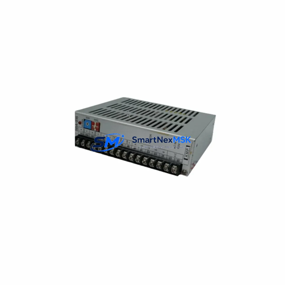
KMP SBA-515 Retrofit-Ready 5-Phase Stepper Driver for SBA Series Control Systems
The KMP SBA-515 is a retrofit-ready, 5-phase stepper motor driver engineered for seamless integration into legacy SBA Series automation systems. As original SBA Series drives reach end-of-life or become increasingly difficult to source, the SBA-515 provides a verified drop-in upgrade path that preserves existing wiring layouts, maintains PLC signal compatibility, and eliminates the need for full control cabinet redesign. Whether you are replacing a failed unit on an active production line or executing a planned modernization of an aging motion control system, the SBA-515 delivers the reliability and compatibility that industrial engineers demand.
Designed for 5-phase stepper motor applications, the SBA-515 supports standard pulse/direction (PUL/DIR) and CW/CCW input modes, making it directly compatible with command outputs from mainstream PLC platforms including Mitsubishi FX Series, Omron CP/CJ Series, Siemens S7-200 SMART, and Delta DVP Series controllers. The driver accepts a wide input voltage range and is housed in a compact DIN rail-mountable enclosure, allowing it to slot directly into existing control cabinet layouts without panel modification.
Upgrade Compatibility Table
| Parameter | Detail |
|---|---|
| Model | KMP SBA-515 |
| Drive Type | 5-Phase Stepper Motor Driver |
| Replaces | SBA Series 5-phase stepper drives (discontinued / EOL models) |
| Input Signal | PUL/DIR or CW/CCW, optically isolated, 5–24V compatible |
| Motor Compatibility | 5-phase stepper motors (standard SBA Series motor wiring) |
| Mounting | DIN rail (35mm), panel mount optional |
| PLC Compatibility | Mitsubishi FX/Q, Omron CP/CJ, Siemens S7-200 SMART, Delta DVP |
| Communication | Pulse-based (standalone); no fieldbus required |
| Wiring Compatibility | Terminal block layout compatible with SBA Series predecessors |
| Installation Requirement | Verify motor phase wiring sequence before power-on |
| Commissioning Note | Re-confirm current setting switches and microstep resolution |
| Warranty | 12 months from date of shipment |
Retrofit Planning for Existing Automation Systems
A successful SBA-515 retrofit begins well before the unit arrives on-site. Engineers should start by auditing the existing control cabinet to document the current stepper driver’s terminal wiring, current setting DIP switches, and microstep resolution configuration. In most SBA Series installations, the stepper driver shares a 24VDC rail with other devices such as the KMP SBA-500 power supply module or a dedicated switching power supply — confirm that the rail has sufficient current headroom to support the SBA-515’s peak draw before proceeding.
The SBA-515 uses a standard 5-phase motor connector pinout. When replacing an older SBA Series driver, technicians should verify the motor phase sequence (A, B, C, D, E) against the existing motor cable labeling. In cases where the original motor is a KMP 5-phase stepper motor from the SBA Series, the wiring is typically direct-compatible. If the motor has been previously rewired or replaced with a third-party 5-phase unit, a phase resistance check with a multimeter is recommended before energizing.
On the PLC side, the high-speed pulse output channel — typically a transistor output (NPN or PNP) on controllers such as the Mitsubishi FX3U or Omron CP1H — connects directly to the SBA-515’s PUL and DIR inputs. No signal converter or intermediate relay is required. If the existing program uses PLSY or DPLSY instructions (Mitsubishi) or PULS/SPED instructions (Omron), these do not need modification. The SBA-515’s optically isolated inputs accept 5V to 24V logic levels, covering the full range of common PLC output voltages.
For systems that also include a KMP SBA Series HMI panel or a third-party touch screen connected via RS-232 or RS-485, the HMI screen layouts and register mappings do not need to change — the SBA-515 does not alter the PLC’s data register structure. However, if the HMI displays drive fault status via a digital input read-back, verify that the SBA-515’s alarm output wiring matches the original driver’s fault signal polarity (normally open vs. normally closed).
In multi-axis systems, where the SBA-515 is installed alongside other motion components such as a KMP SBA-510 servo driver, a KMP SBA-520 stepper indexer, or additional I/O expansion modules on the same backplane or DIN rail section, ensure that each driver’s address or axis assignment is correctly set before running the motion program. Axis address conflicts are a common source of commissioning delays in multi-drive retrofits.
Before closing the cabinet, perform a full pre-power checklist: confirm terminal torque on all screw connections, verify that the motor cable shield is grounded at one end only, and check that the 24VDC common (COM) is shared correctly between the PLC output module and the SBA-515 input circuit. A brief jog test at low speed and reduced current is recommended before restoring full production parameters.
Downtime Control During System Migration
Minimizing unplanned downtime is the primary concern in any stepper drive replacement. The SBA-515’s wiring compatibility with legacy SBA Series drives means that a prepared technician can complete a like-for-like swap in under 30 minutes on a pre-documented system. The key to achieving this is advance preparation: photograph the existing wiring before removal, record all DIP switch positions (current setting, microstep resolution, self-test mode), and back up the PLC program to a laptop or memory cassette — for example, using a Mitsubishi FX-USB-AW programming cable or an Omron CX-Programmer backup file — before touching any hardware.
Where production schedules allow only a narrow maintenance window, consider staging the SBA-515 on a bench test rig with a spare 5-phase stepper motor to verify correct rotation direction and step count before the scheduled outage. This eliminates on-site troubleshooting time and allows the field team to focus entirely on the physical swap and final verification during the actual downtime window.
After installation, restore the PLC program from backup, confirm the HMI communication link is active, and run a slow-speed jog cycle to verify motor direction and step accuracy before returning the axis to automatic mode. Document the new DIP switch settings and update the cabinet wiring diagram to reflect the SBA-515 installation. This record becomes essential for future maintenance and for any subsequent upgrade to a KMP closed-loop stepper system or servo-based replacement platform.
All SBA-515 units shipped by SMARTNEXMSK are tested under load prior to dispatch. Each unit includes a 12-month warranty covering manufacturing defects, with technical support available for commissioning assistance.
Retrofit Support FAQ
Q1: Is the KMP SBA-515 a direct replacement for my existing SBA Series stepper driver?
In most SBA Series installations, yes. The SBA-515 shares the same terminal block layout, motor connector pinout, and PUL/DIR signal interface as the standard SBA Series 5-phase driver family. Confirm your motor’s phase count (5-phase) and your PLC’s output voltage level before ordering. If your existing driver uses a non-standard wiring configuration, contact our technical team with your cabinet drawing for a pre-sale compatibility review.
Q2: Do I need to modify my PLC program after installing the SBA-515?
No program modification is required in standard pulse/direction applications. The SBA-515 accepts the same PUL/DIR or CW/CCW signals as the original driver. Verify that the pulse frequency does not exceed the SBA-515’s maximum input frequency specification, and confirm that the PLC output type (NPN/PNP) matches the driver’s input wiring configuration.
Q3: What should I check during commissioning after the swap?
After installation, verify: (1) motor phase wiring sequence and rotation direction at low speed, (2) current setting DIP switches match the motor’s rated phase current, (3) microstep resolution matches the original setting to preserve position scaling in the PLC program, (4) alarm output wiring polarity matches the PLC input expectation, and (5) the 24VDC supply voltage is within specification under load.
Q4: What does the 12-month warranty cover, and how is it handled?
The 12-month warranty covers manufacturing defects in materials and workmanship from the date of shipment. All units are tested under load before dispatch. In the event of a warranty claim, contact SMARTNEXMSK with the order reference and a description of the fault. Replacement units are dispatched after fault verification. The warranty does not cover damage resulting from incorrect wiring, overvoltage, or mechanical impact.
© 2026 SMARTNEXMSK. All rights reserved.
Original Source: https://smartnexmsk.com
Contact: sales@smartnexmsk.com | +86 18259474341