KOBERLEIN RMA-POWER-BOX 107/230 Spare for RMA Automation
The KOBERLEIN RMA-POWER-BOX 107/230 is a precision vibratory drive controller engineered for continuous-duty industrial feeding and conveying systems. As a maintenance-ready original spare, this unit is stocked to support rapid replacement in RMA-series vibratory feeder installations where unplanned downtime directly impacts production throughput. Whether you are executing a planned shutdown, responding to a controller fault, or building a critical-path spare inventory, the RMA-POWER-BOX 107/230 delivers verified compatibility, tested output, and a 12-month warranty from date of shipment.
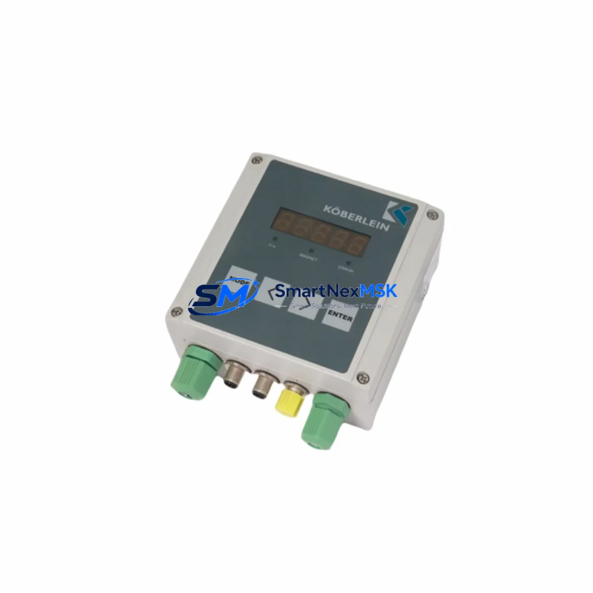
Maintenance engineers and procurement teams working on KOBERLEIN RMA-series bowl feeders, linear feeders, and vibratory conveyors recognize the RMA-POWER-BOX 107/230 as the primary power and frequency control unit governing amplitude and feed rate. When this controller fails or degrades, the entire feeding line stops — making fast, like-for-like replacement the only viable recovery path. Our stock is sourced from authorized channels, inspected before dispatch, and shipped with full documentation to support your maintenance records.
Spare Maintenance Table
| Parameter | Specification |
|---|---|
| SKU / Part Number | RMA-POWER-BOX 107/230 |
| Brand | KOBERLEIN |
| Series | RMA |
| Product Type | Vibratory Drive Controller |
| Input Voltage | 230 V AC, 50/60 Hz (single-phase) |
| Output Power | 107 W rated drive output |
| Control Function | Amplitude / frequency regulation for vibratory feeders |
| Origin | Germany (DE) |
| Weight | 1,280 g |
| Compatibility | KOBERLEIN RMA-series bowl feeders, linear feeders, vibratory conveyors |
| Installation | Panel-mount or DIN-rail compatible enclosure; refer to OEM wiring diagram |
| Application Environment | Industrial automation, assembly lines, pharmaceutical, food processing, electronics manufacturing |
| Maintenance Recommendation | Inspect every 12 months or after any overcurrent event; replace potentiometer and terminal blocks if worn |
| Warranty | 12 months from date of shipment |
| Pre-shipment Test | Function-tested and inspected before dispatch |
Maintenance Planning for Continuous Operation
When replacing the RMA-POWER-BOX 107/230, a thorough site inspection of the surrounding electrical circuit is essential to prevent repeat failures and ensure the replacement unit operates within its rated parameters. Maintenance engineers should treat this replacement as an opportunity to audit the full feeder control loop.
Begin with the incoming power supply: verify that the 230 V AC supply rail is stable and within ±10% tolerance. A degraded or fluctuating supply is a common root cause of controller failure in vibratory feeder circuits. Check the line fuse or circuit breaker feeding the RMA-POWER-BOX — a blown or weakened fuse may indicate a prior overcurrent event that also stressed the controller. Replace the fuse as a matter of course during any controller swap.
Inspect the output wiring to the vibratory drive coil: look for insulation breakdown, loose terminal connections, or corroded ferrules on the terminal block assembly. Loose connections at the drive coil terminals are a frequent cause of intermittent amplitude loss and can damage a new controller within weeks if not corrected. If the terminal block shows signs of heat discoloration or mechanical wear, replace it alongside the RMA-POWER-BOX 107/230.
For installations where the RMA-POWER-BOX is integrated into a larger PLC-controlled line, verify the control signal interface: the 0–10 V or 4–20 mA analog setpoint signal from the PLC analog output module should be clean and within range. A drifting or noisy analog signal will cause erratic feed rates even with a new controller installed. If the PLC analog output card is aging, consider scheduling its replacement during the next planned maintenance window.
Where the feeder is part of a synchronized conveying system, check the communication module or relay interface that coordinates the feeder start/stop signal with upstream and downstream equipment. A faulty output relay or interlock relay in the control cabinet can prevent the new RMA-POWER-BOX from receiving its enable signal, causing apparent controller failure on first power-up.
For cabinets housing multiple KOBERLEIN RMA-series controllers — such as installations with both a bowl feeder and a linear feeder — inspect the shared power distribution block and any signal isolation modules used to separate the analog setpoint channels. Cross-talk or ground loops between channels can cause instability across all controllers in the cabinet. A signal isolator rated for 0–10 V or 4–20 mA should be part of your standard spare inventory for these multi-axis feeder panels.
Finally, if the installation includes an HMI panel for operator speed adjustment, verify that the HMI analog output or digital potentiometer interface is functioning correctly after the controller replacement. An HMI with a failed output stage will prevent operators from adjusting feed rate, even though the RMA-POWER-BOX itself is fully operational. Keeping a spare HMI interface card or operator panel in your maintenance kit is recommended for high-availability feeder lines.
Site Replacement Workflow
Step 1 — Isolate and de-energize: Switch off the feeder circuit breaker and lock out / tag out (LOTO) the supply. Confirm zero voltage at the RMA-POWER-BOX input terminals with a calibrated multimeter before proceeding.
Step 2 — Document existing wiring: Photograph or sketch the terminal connections on the outgoing unit before disconnecting any wires. The RMA-POWER-BOX 107/230 terminal layout should match the replacement unit, but confirming wire positions eliminates re-wiring errors.
Step 3 — Remove the failed unit: Disconnect input power, output drive coil wires, and control signal wires. Remove the controller from its mounting position. Retain the mounting hardware.
Step 4 — Install the replacement RMA-POWER-BOX 107/230: Mount the new unit, reconnect all terminals per your documented wiring layout, and torque terminal screws to the manufacturer’s specification. Do not over-tighten — stripped terminals are a common installation error.
Step 5 — Pre-power checks: Verify supply voltage, confirm fuse rating, and check that the amplitude potentiometer is set to minimum before energizing. This protects the drive coil from a sudden full-amplitude surge on first power-up.
Step 6 — Commission and test: Restore power, gradually increase amplitude to the operating setpoint, and confirm stable feed rate. Monitor for abnormal heat, vibration, or current draw during the first 15 minutes of operation.
This workflow is compatible with direct replacement of legacy KOBERLEIN RMA-series controllers and supports system continuity without requiring PLC program changes or mechanical modifications to the feeder bowl or drive assembly.
Spare Parts Support FAQ
Q1: Is the RMA-POWER-BOX 107/230 a direct drop-in replacement for older RMA-series controllers?
Yes. The RMA-POWER-BOX 107/230 is designed as a direct replacement for compatible KOBERLEIN RMA-series vibratory drive controllers with the same voltage and power rating. Terminal layout and mounting dimensions are consistent across the RMA product family. Always verify the input voltage (230 V) and output power (107 W) against your existing unit’s nameplate before installation.
Q2: What pre-shipment testing is performed on each unit?
Every RMA-POWER-BOX 107/230 is function-tested before dispatch. Testing includes input voltage verification, output amplitude response, and potentiometer range check. Units that do not meet performance criteria are quarantined and not shipped. A test record is available upon request for quality-critical applications.
Q3: How should I manage spare inventory for a multi-feeder installation?
For installations with three or more KOBERLEIN RMA-series feeders, we recommend maintaining at least one RMA-POWER-BOX 107/230 as a hot spare on-site. Mean time between failures (MTBF) for vibratory drive controllers in continuous-duty applications typically ranges from 3 to 7 years depending on ambient temperature, supply quality, and load cycling. A single on-site spare eliminates the lead-time risk associated with emergency procurement and supports same-shift recovery from an unplanned controller failure.
Q4: What does the 12-month warranty cover?
The 12-month warranty covers manufacturing defects, component failure under normal operating conditions, and any unit that fails to perform to its rated specification. The warranty does not cover damage caused by incorrect installation, supply voltage outside the rated range, or physical damage in transit after delivery. Warranty claims are processed promptly — contact our support team with your order number and a description of the fault, and we will arrange a replacement or repair within the agreed service window.
© 2026 SMARTNEXMSK. All rights reserved.
Original Source: https://smartnexmsk.com
Contact: sales@smartnexmsk.com | +86 18259474341