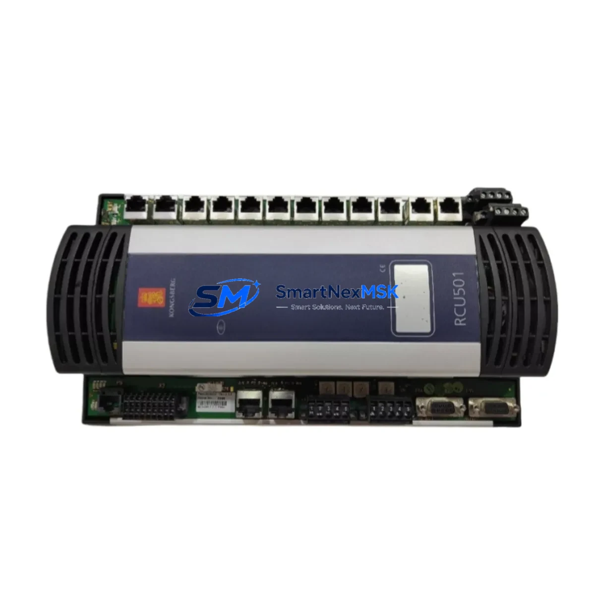
KONGSBERG RCU501 Spare for K-Chief Series Automation
The KONGSBERG RCU501 Remote Controller Unit is a critical spare component within the K-Chief vessel automation and dynamic positioning ecosystem. Designed for continuous-duty marine and industrial control environments, the RCU501 serves as the operator interface and command relay node between the K-Chief 500/600 series automation backbone and field-level I/O, alarm management, and propulsion control subsystems. When an RCU501 fails or degrades, the entire control station loses supervisory capability — making rapid, like-for-like replacement essential to minimizing vessel downtime and restoring safe operational status.
At SMARTNEXMSK, every RCU501 unit is sourced from verified supply channels, individually bench-tested against KONGSBERG factory communication and I/O specifications, and shipped with a 12-month warranty. Our inventory is maintained specifically to support emergency replacement, planned dry-dock maintenance, and long-term lifecycle extension of legacy K-Chief installations.
Spare Maintenance Table
| Parameter | Specification |
|---|---|
| Part Number / SKU | RCU501 |
| Full Description | Remote Controller Unit |
| Brand | KONGSBERG Maritime |
| Compatible Series | K-Chief 500, K-Chief 600, SDP (Dynamic Positioning) |
| Communication Interface | RS-485 / Ethernet (system-dependent configuration) |
| Operating Voltage | 24 VDC (nominal, system-supplied) |
| Operating Temperature | 0°C to +55°C (control room / bridge environment) |
| Mounting | Panel-mount / console-integrated |
| Origin | Norway (NO) |
| Application Environment | Marine vessel automation, offshore DP systems, industrial control rooms |
| Compatibility Verification | Cross-referenced against K-Chief 500/600 BOM and SDP system documentation |
| Pre-shipment Testing | Communication handshake, I/O response, display function, alarm relay |
| Warranty | 12 Months from date of shipment |
| Lead Time | In stock — typically ships within 1–3 business days |
Maintenance Planning for Continuous Operation
Maintenance engineers planning an RCU501 replacement should treat the intervention as a system-level inspection opportunity, not an isolated swap. The RCU501 interfaces directly with the K-Chief automation network, and its failure mode — whether sudden loss of display, communication timeout, or intermittent alarm relay dropout — often reflects stress on adjacent components that share the same 24 VDC power rail or communication bus.
Before or during an RCU501 replacement, the following components should be inspected and, where condition warrants, replaced as part of the same maintenance window:
- K-Chief Power Supply Module (PSU) — Verify output voltage stability under load. A degraded PSU is a common root cause of RCU controller brownouts and communication faults.
- Alarm Management Unit (AMU) / Alarm Panel — Confirm alarm relay continuity and that the AMU correctly receives status signals from the replacement RCU501.
- I/O Extension Modules — Inspect digital and analog I/O cards connected to the same backplane or DIN rail segment. Loose terminal connections or oxidized contacts can cause false alarms post-replacement.
- Communication Gateway / Network Switch — Validate Ethernet or RS-485 bus integrity. A faulty network switch or corroded bus terminator can prevent the new RCU501 from establishing communication with the K-Chief server.
- Operator Station HMI Panel — If the vessel uses a dedicated HMI touchscreen alongside the RCU501, verify that the HMI firmware version is compatible with the replacement unit’s communication protocol revision.
- Signal Isolators and Barriers — Check signal isolators on analog sensor loops feeding into the RCU501. Degraded isolators introduce noise that can cause erratic readings or spurious alarms after a controller replacement.
- Terminal Blocks and Wiring Harness — Inspect all terminal block connections at the RCU501 connector points. Re-torque to specification and replace any discolored or heat-stressed terminals.
- Fuse and Circuit Protection — Verify fuse ratings and condition on the 24 VDC supply line to the RCU501. Replace any fuses showing signs of thermal stress.
- Backplane / Rack Assembly — If the RCU501 is rack-mounted, inspect the backplane connector for pin damage or corrosion, particularly in high-humidity marine environments.
- SDP Joystick Controller / DP Reference Unit — For vessels where the RCU501 is integrated into the dynamic positioning control loop, confirm that the DP reference sensors and joystick controller are communicating correctly after the RCU501 is restored to service.
Stocking a spare RCU501 alongside a spare PSU and at least one I/O module is the recommended minimum inventory posture for vessels operating K-Chief 500/600 systems beyond their original design lifecycle. This approach ensures that a single-component failure does not cascade into a multi-day procurement delay.
Site Replacement Workflow
Step 1 — Pre-replacement documentation: Record the current RCU501 configuration parameters, including station address, alarm group assignments, and any custom display page layouts, using the K-Chief configuration backup utility before powering down.
Step 2 — Power isolation: Isolate the 24 VDC supply to the RCU501 at the dedicated circuit breaker or fuse holder. Confirm isolation with a calibrated multimeter before disconnecting any wiring.
Step 3 — Physical removal: Disconnect the communication bus connector and all I/O wiring, labeling each conductor. Remove the RCU501 from its panel or rack mount, noting the orientation and any mechanical retention features.
Step 4 — Replacement unit preparation: Verify that the replacement RCU501 SKU matches the failed unit’s hardware revision. Load the backed-up configuration file if the K-Chief system supports remote configuration restore; otherwise, manually re-enter station parameters.
Step 5 — Installation and wiring: Mount the replacement unit, reconnect all labeled conductors to the correct terminals, and re-engage the communication bus connector. Confirm terminal torque to specification.
Step 6 — Power-up and commissioning: Restore 24 VDC supply and observe the RCU501 boot sequence. Confirm communication link establishment with the K-Chief server, verify alarm relay function, and perform a full I/O scan to confirm all connected field devices are reporting correctly.
Step 7 — System handover: Document the replacement in the vessel’s maintenance log, including the new unit’s serial number, date of installation, and warranty expiry. Retain the failed unit for root-cause analysis if required by class or flag state.
This workflow is designed to minimize control system downtime to under four hours for a prepared maintenance team, and to ensure full system compatibility without requiring a class surveyor intervention in most jurisdictions.
Spare Parts Support FAQ
Q1: How do I confirm that this RCU501 is compatible with my specific K-Chief installation?
Provide your vessel name, K-Chief system version (500 or 600 series), and the hardware revision number printed on the failed unit’s label. Our technical team will cross-reference against the K-Chief BOM and confirm compatibility before shipment. We do not ship units where compatibility cannot be verified.
Q2: What does the 12-month warranty cover, and how is a warranty claim processed?
The 12-month warranty covers manufacturing defects and functional failures under normal operating conditions. It does not cover damage caused by incorrect installation, overvoltage, or physical impact. To initiate a claim, contact sales@smartnexmsk.com with the order number, failure description, and photographic evidence. Replacement or repair is typically arranged within 5 business days of claim approval.
Q3: Can I stock this unit as a long-term spare without immediate installation?
Yes. The RCU501 should be stored in its original anti-static packaging in a dry, temperature-controlled environment (5°C to 40°C, <75% RH non-condensing). Stored units should be powered up and functionally tested at least once every 24 months to verify capacitor health and communication module integrity. The 12-month warranty period begins from the date of shipment, not the date of installation.
Q4: What pre-shipment testing is performed on each unit?
Every RCU501 dispatched from SMARTNEXMSK undergoes a structured test protocol: power-on self-test, communication bus handshake verification, digital I/O relay function check, display output confirmation, and alarm signal relay test. A test report is available upon request and can be included with the shipment documentation for class or flag state records.
© 2026 SMARTNEXMSK. All rights reserved.
Original Source: https://smartnexmsk.com
Contact: sales@smartnexmsk.com | +86 18259474341