KRB 1F144-0-LED-NC-US0E Spare for 1F144 Automation: Spare Parts Replacement & Industrial Downtime Risk Control
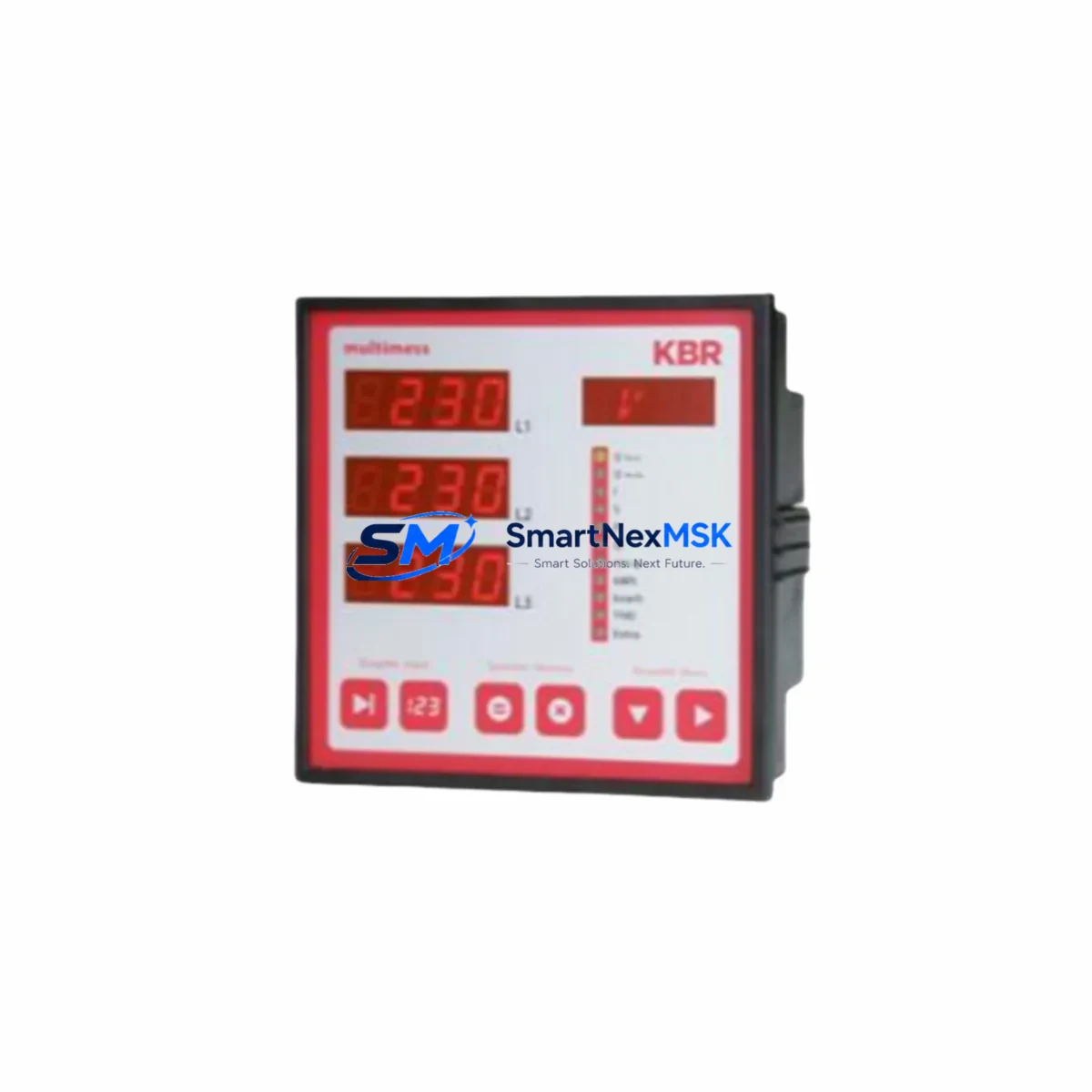
The KRB 1F144-0-LED-NC-US0E is a DIN 144 format single-phase active energy meter from KRB’s 1F144 series, featuring an LED pulse output and NC (normally closed) relay output. Designed for continuous duty in industrial panel environments, this unit is widely deployed in factory power distribution boards, motor control centers, and utility sub-metering systems. When this meter reaches end-of-life or fails in service, a verified original spare must be available to restore measurement accuracy and relay-based load control without delay.
For maintenance engineers and procurement teams managing aging control systems, stocking the 1F144-0-LED-NC-US0E as a ready spare eliminates the risk of extended downtime caused by meter failure. This unit ships tested and verified, with a 12-month warranty covering manufacturing defects and functional performance.
Spare Maintenance Table
| Parameter | Specification |
|---|---|
| SKU / Model | 1F144-0-LED-NC-US0E |
| Brand | KRB |
| Series | 1F144 (DIN 144 Format) |
| Product Type | Single-Phase Active Energy Meter |
| Output Type | NC Relay Output + LED Pulse Output |
| Mounting Format | DIN 144 Panel Mount |
| Application | Industrial Power Sub-Metering, MCC Panels, Distribution Boards |
| Compatibility | Drop-in replacement for 1F144 series meters with NC relay configuration |
| Origin | China (CN) |
| Warranty | 12 Months — Covers manufacturing defects and functional performance |
| Shipping Condition | Tested and verified before dispatch |
| Maintenance Recommendation | Inspect relay contacts and pulse output wiring at each planned maintenance interval; replace meter if pulse count deviation exceeds ±1% |
Maintenance Planning for Continuous Operation
When replacing the KRB 1F144-0-LED-NC-US0E in a live panel, a thorough inspection of the surrounding electrical circuit is essential to prevent repeat failures and ensure measurement integrity. Maintenance engineers should treat this replacement as an opportunity to audit the full metering and control loop.
Begin by verifying the incoming supply voltage and current transformer (CT) secondary wiring. A loose or open CT secondary during meter swap can generate dangerous voltage spikes and corrupt energy readings. Inspect the terminal block connections — DIN rail-mounted terminal strips adjacent to the meter are common points of oxidation and contact resistance buildup, particularly in humid or high-vibration environments.
The NC relay output of the 1F144-0-LED-NC-US0E is typically wired into an intermediate relay or solid-state relay (SSR) for load control or alarm triggering. Verify that the downstream relay coil voltage matches the meter’s relay output rating and that the relay itself is not showing signs of contact wear or coil degradation. In many installations, a KRB or compatible auxiliary relay module is mounted in the same panel section — this should be tested for proper pick-up and drop-out during the maintenance window.
The LED pulse output is commonly connected to a pulse counter input on a PLC or data acquisition module. Confirm that the pulse input card — often a digital input module in a Siemens S7, Mitsubishi FX, or Omron CP series PLC — is reading pulses correctly after meter replacement. A mismatch in pulse constant (imp/kWh) between the old and new meter will cause energy accounting errors that may not be immediately visible.
For panels with multiple energy meters, also inspect neighboring 1F144 series meters of different configurations (e.g., 1F144-0-LED-NO-US0E with NO relay output) to confirm they are within calibration tolerance. If the panel includes a power quality analyzer or harmonic meter, verify that its CT inputs are undisturbed during the swap.
Procurement engineers should also consider stocking complementary components: DIN rail fuse holders and 2A glass fuses for meter supply protection, shorting terminal blocks for CT circuits, and surge protection devices (SPDs) on the supply input to protect sensitive metering electronics from transient overvoltages. Where the meter feeds data to an HMI or SCADA system via pulse counting, ensure the signal cable shielding and grounding are intact to prevent pulse count noise.
Site Replacement Workflow
Step 1 — Pre-replacement verification: Confirm the replacement unit SKU is 1F144-0-LED-NC-US0E and that the relay output type (NC) matches the existing wiring scheme. Do not substitute an NO-output variant without rewiring the downstream relay circuit.
Step 2 — CT secondary shorting: Before disconnecting the old meter, short the CT secondary terminals using a certified CT shorting link. This is a mandatory safety step that prevents open-circuit CT voltage hazards.
Step 3 — Terminal labeling and photo documentation: Photograph the existing wiring before removal. Label all conductors — supply L/N, CT S1/S2, relay output, and pulse output — to ensure correct reconnection to the new unit.
Step 4 — Meter removal and installation: Remove the old 1F144-0-LED-NC-US0E from the DIN 144 panel cutout. Install the replacement unit, reconnect all terminals per the original wiring diagram, and remove the CT shorting link.
Step 5 — Functional verification: Apply power and verify that the meter display initializes correctly, the LED pulse output is active under load, and the NC relay output is in the correct state. Cross-check the pulse count against a reference meter or clamp meter reading over a 5-minute interval to confirm accuracy.
Step 6 — System re-integration: Reset the energy accumulation register if required by site protocol. Update the maintenance log with the replacement date, new meter serial number, and post-installation test results. Notify the SCADA or BMS operator to re-zero the energy sub-meter channel if applicable.
This workflow minimizes panel downtime to under 30 minutes for a trained technician and ensures full system compatibility is maintained without PLC program changes or HMI reconfiguration.
Spare Parts Support FAQ
Q1: Is the 1F144-0-LED-NC-US0E a direct drop-in replacement for older 1F144 series meters?
Yes. The 1F144-0-LED-NC-US0E maintains the same DIN 144 panel cutout dimensions and terminal layout as earlier 1F144 series production runs. No panel modification is required for a like-for-like replacement, provided the relay output type (NC) matches the original installation.
Q2: How is the unit tested before shipment?
Each unit undergoes functional verification prior to dispatch, including display initialization, relay output continuity, and LED pulse output confirmation under simulated load conditions. A test record is available upon request for quality-critical installations.
Q3: What does the 12-month warranty cover?
The warranty covers manufacturing defects and functional failures under normal operating conditions for 12 months from the date of shipment. It does not cover damage resulting from incorrect installation, overvoltage events, or CT open-circuit conditions. Warranty claims are processed with return of the defective unit and provision of installation documentation.
Q4: Can you support long-term or blanket purchase orders for ongoing spare parts inventory?
Yes. For maintenance teams managing multiple panels or multi-site installations, we support scheduled delivery agreements and reserved stock arrangements. Contact our team to discuss volume pricing, lead time commitments, and consignment stock options for the 1F144-0-LED-NC-US0E and related 1F144 series components.
© 2026 SMARTNEXMSK. All rights reserved.
Original Source: https://smartnexmsk.com
Contact: sales@smartnexmsk.com | +86 18259474341