KWANGWOO RAA-001007-2102 Retrofit-Ready Rotary Encoder for RAA Series Control Systems
The KWANGWOO RAA-001007-2102 is a precision rotary encoder engineered for seamless integration into legacy RAA series automation and motion control systems. As industrial facilities face increasing pressure to modernize aging control infrastructure without full-line shutdowns, the RAA-001007-2102 delivers a verified drop-in replacement path that preserves existing wiring layouts, signal protocols, and mechanical mounting configurations. Whether you are replacing a failed unit on a production line, upgrading a discontinued encoder in a multi-axis servo system, or migrating an entire control cabinet to a newer platform, this encoder is designed to minimize engineering rework and reduce total retrofit cost.
Sourced directly from authorized supply channels and fully tested prior to shipment, each RAA-001007-2102 unit is backed by a 12-month warranty covering manufacturing defects and signal integrity. Stock is maintained in Xiamen for rapid dispatch to domestic and international customers operating in manufacturing, packaging, printing, CNC machining, and process automation environments.
Upgrade Compatibility Table
| Parameter | Detail |
|---|---|
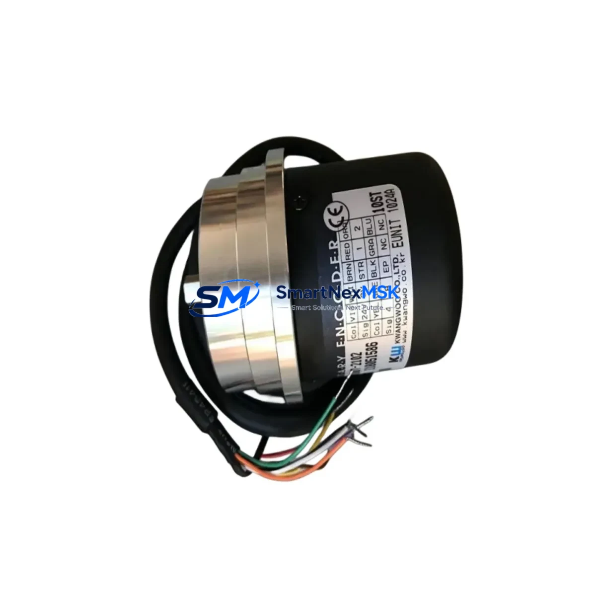
| SKU / Part Number | RAA-001007-2102 |
| Brand | KWANGWOO |
| Series | RAA Series |
| Product Type | Rotary Encoder (Incremental) |
| Origin | South Korea (KR) |
| Signal Interface | Compatible with standard A/B/Z incremental encoder inputs on RAA series controllers |
| Mounting | Direct replacement — existing bracket and shaft coupling retained |
| Wiring Compatibility | Terminal pinout matches RAA series encoder input modules; verify supply voltage (5 VDC / 12 VDC / 24 VDC) before installation |
| Communication Compatibility | Compatible with PLC encoder input cards accepting TTL/HTL differential signals |
| Replacement Recommendation | Suitable for direct substitution of discontinued RAA series encoders; confirm resolution (PPR) matches original specification |
| Commissioning Notes | Verify zero-point reference (Z-pulse) alignment after installation; re-home axes before resuming production |
| Warranty | 12 Months — covers manufacturing defects and signal output integrity |
Retrofit Planning for Existing Automation Systems
Successful integration of the RAA-001007-2102 into an existing control system requires a structured pre-installation review. Begin by auditing the encoder input card installed in your control cabinet — common configurations include dedicated encoder interface modules mounted on the main backplane of the motion controller or PLC rack. Confirm that the input card supports the resolution (pulses per revolution) of the RAA-001007-2102 and that the supply voltage rail matches the encoder’s operating range.
In systems where the RAA series encoder feeds directly into a servo drive — such as those using KWANGWOO servo amplifiers or compatible third-party drives — verify that the drive’s encoder feedback parameter settings do not require reconfiguration after the swap. Many servo drives store encoder type and resolution in non-volatile memory; a parameter backup using the drive’s programming software or a dedicated programming cable is strongly recommended before any hardware change.
For control cabinets that integrate the encoder signal through a terminal block distribution board or signal conditioner, inspect the existing terminal wiring against the RAA-001007-2102 pinout diagram. In multi-axis systems, it is common to find encoder signals routed through a backplane bus or a dedicated I/O expansion rack. Ensure that the module address assigned to the encoder input channel is preserved in the PLC program — address conflicts after hardware replacement are a frequent source of commissioning delays.
Where the control system includes an HMI panel displaying position, speed, or count data derived from the encoder, verify that the HMI screen tags remain correctly mapped after the replacement. In systems using communication protocols such as PROFIBUS, EtherNet/IP, or Modbus RTU for encoder data transmission through a gateway module, confirm that the gateway configuration does not require re-parameterization. Power supply modules feeding the encoder circuit should also be checked — ensure the 24 VDC rail has sufficient current headroom, particularly in cabinets where multiple encoders, proximity sensors, and I/O modules share the same supply bus.
Commonly required companion components during RAA series encoder retrofits include: encoder input interface modules, servo drive parameter backup cables, terminal block wiring accessories, DIN rail mounting hardware, cable shielding clamps for noise suppression, 24 VDC power supply modules, I/O expansion modules for signal distribution, motion controller backplane connectors, HMI communication cables, and encoder signal repeaters for long cable runs. Sourcing these components in advance significantly reduces on-site retrofit time.
Downtime Control During System Migration
Minimizing production downtime during an encoder replacement requires preparation that begins well before the maintenance window. The first priority is a full backup of the PLC program, including all data blocks, motion profiles, and encoder-referenced position registers. This backup should be stored on both the programming laptop and an offline archive — a step that protects against accidental program loss if the controller loses power during the swap.
Before removing the failed or obsolete encoder, document the existing wiring with photographs and a written terminal map. Label each wire individually if the existing installation does not already use numbered ferrules. This documentation eliminates ambiguity during reconnection and is especially critical in cabinets where multiple encoder channels share a common cable conduit.
During the physical swap, keep the machine in a safe, de-energized state with lockout/tagout procedures applied. After installing the RAA-001007-2102 and reconnecting the wiring, perform a signal verification test before re-enabling the drive or motion controller — use a handheld encoder tester or the diagnostic function of the PLC’s encoder input module to confirm that A, B, and Z pulse outputs are clean and correctly phased. Once signal integrity is confirmed, restore power to the drive, re-home all affected axes, and run a slow-speed test cycle before returning the machine to full production speed. This structured approach consistently achieves encoder replacements within a single planned maintenance shift, keeping unplanned downtime to a minimum.
Retrofit Support FAQ
Q1: Is the RAA-001007-2102 a direct drop-in replacement for my existing RAA series encoder?
In most RAA series applications, yes — the mechanical dimensions, shaft diameter, and mounting flange are consistent across the RAA product family. However, you must confirm that the resolution (PPR) and output signal type (TTL or HTL) of the RAA-001007-2102 match your original specification before installation. If your original encoder used a different PPR value, the motion controller’s position scaling parameters will need to be updated accordingly.
Q2: What wiring checks are required before powering up after installation?
Verify supply voltage polarity and level (5 V, 12 V, or 24 V depending on your system), confirm that the A, B, and Z signal wires are connected to the correct terminals on the encoder input card, and ensure that the cable shield is grounded at the control cabinet end only (single-point grounding) to prevent noise interference. Do not power up the encoder until all terminal connections have been torqued to specification and visually inspected.
Q3: How do I verify compatibility with my PLC or motion controller before ordering?
Provide us with your existing encoder part number, the make and model of your PLC or motion controller, and the encoder input card type currently installed. Our technical team will cross-reference the RAA-001007-2102 specifications against your system requirements and confirm compatibility in writing before shipment. Contact: sales@smartnexmsk.com or +86 18259474341.
Q4: What does the 12-month warranty cover, and what is the process for a warranty claim?
The 12-month warranty covers manufacturing defects, signal output failures, and mechanical integrity issues under normal operating conditions. It does not cover damage resulting from incorrect wiring, overvoltage, physical impact, or installation errors. To initiate a warranty claim, contact our sales team with your order reference, a description of the fault, and photographs of the installation. Replacement units are dispatched after fault verification, with return shipping coordinated by our logistics team.
© 2026 SMARTNEXMSK. All rights reserved.
Original Source: https://smartnexmsk.com
Contact: sales@smartnexmsk.com | +86 18259474341