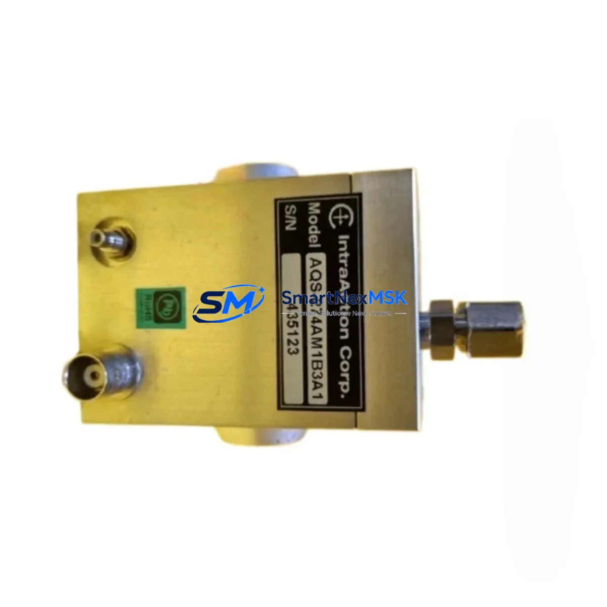
LEE LASER AQS-274AM1B3A1 Retrofit-Ready Q-Switch for AQS Series Control Systems
The LEE LASER AQS-274AM1B3A1 is a precision acousto-optic Q-switch module engineered for seamless integration into existing AQS Series laser control platforms. Whether you are replacing an end-of-life unit, upgrading a legacy pulsed laser system, or restoring a production line after an unplanned failure, the AQS-274AM1B3A1 delivers verified drop-in compatibility with minimal reconfiguration. With a 12-month warranty and pre-shipment functional testing, this module is a trusted solution for maintenance engineers and system integrators managing laser-based manufacturing, marking, and materials processing equipment.
Designed to interface directly with the AQS Series driver electronics, the AQS-274AM1B3A1 maintains the RF drive frequency, impedance matching, and optical aperture specifications of the original factory-installed unit. Replacement planning should confirm the RF driver output power level — typically 2–3 W for this class of Q-switch — and verify that the existing coaxial cable assembly and SMA or BNC connector termination are in serviceable condition before installation. Mismatched RF impedance or a degraded cable can reduce diffraction efficiency and shorten module service life even on a new replacement unit.
During retrofit, engineers should also inspect the laser head mounting bracket and the Q-switch’s optical alignment relative to the resonator axis. The AQS-274AM1B3A1 uses a fused silica TeO₂ crystal optimized for the 1064 nm Nd:YAG wavelength range, consistent with the broader AQS Series product family. If the system previously used an AQS-274AM1B2A1 or an earlier AQS-274 variant, the mechanical footprint and beam aperture are compatible, though the RF frequency specification should be cross-referenced against the driver module — commonly the LEE LASER RFD-Series RF driver — to confirm tuning alignment before power-on.
Upgrade Compatibility Table
| Parameter | AQS-274AM1B3A1 (This Unit) | Notes / Retrofit Guidance |
|---|---|---|
| Crystal Material | TeO₂ (Fused Silica) | Compatible with 1064 nm Nd:YAG systems |
| RF Drive Frequency | Confirm with RFD-Series driver | Verify against existing driver spec sheet |
| RF Connector | SMA / BNC (application-dependent) | Inspect cable assembly before swap |
| Optical Aperture | Compatible with AQS Series beam path | Re-align after installation |
| Mechanical Fit | Drop-in for AQS-274 variants | Cross-check with AQS-274AM1B2A1 if applicable |
| Communication / Control | Passive RF-driven (no digital bus) | No firmware or protocol changes required |
| Replacement Scope | Direct OEM replacement | Suitable for AQS Series laser heads |
| Pre-Shipment Testing | Functional RF and optical test | Test report available on request |
| Warranty | 12 Months | Covers manufacturing defects |
Retrofit Planning for Existing Automation Systems
Laser systems incorporating the AQS-274AM1B3A1 are typically embedded within larger automated production cells where the Q-switch interfaces with a laser controller, a beam delivery assembly, and a motion or PLC-based sequencing system. Before initiating a Q-switch replacement, the maintenance team should document the current pulse repetition rate, gate signal timing from the laser controller, and the interlock status from the machine safety relay chain. In many installations, the Q-switch gate signal originates from a dedicated laser controller board — such as the LEE LASER LC-Series controller — which manages pulse timing relative to the motion axis encoder feedback.
The RF driver module, often mounted in the laser power supply cabinet alongside the diode pump driver and the thermal controller board, must be powered down and discharged before the Q-switch is removed. Technicians should also note the position of the beam dump and shutter assembly, as these components may need to be repositioned if the replacement unit’s optical axis requires minor angular correction. In systems where the laser head is integrated with a galvo scanner or a fixed-focus F-theta lens assembly, even a small misalignment of the Q-switch can produce measurable beam quality degradation at the workpiece.
For production lines that use a fiber-coupled delivery system rather than a free-space beam path, the Q-switch replacement procedure is generally more straightforward, as the fiber coupling alignment is maintained by the laser head housing. However, the output power and M² beam quality should be verified with a power meter and beam profiler after installation before returning the system to production. If the system includes a wavelength conversion stage — such as a second-harmonic generation (SHG) crystal assembly for 532 nm output — the Q-switch pulse width and peak power characteristics of the AQS-274AM1B3A1 should be confirmed against the SHG crystal’s damage threshold specification.
Spare parts commonly staged alongside the AQS-274AM1B3A1 during a planned laser system overhaul include the LEE LASER RFD-Series RF driver, the pump diode module, the resonator mirror set, the laser power supply unit, and the thermal management assembly including the chiller interface fittings. Having these components available on-site reduces the risk of extended downtime if secondary failures are discovered during the Q-switch replacement procedure.
Downtime Control During System Migration
Minimizing production downtime during a Q-switch replacement requires a structured pre-maintenance checklist and a clear return-to-service protocol. Before the maintenance window begins, the engineering team should back up the laser controller parameter file — including pulse energy setpoints, repetition rate tables, and interlock configuration — to ensure that the system can be restored to its previous operating state without manual re-entry of parameters. In systems where the laser controller communicates with a supervisory PLC or SCADA system via a serial or Ethernet link, the communication link should be verified as part of the post-installation commissioning sequence.
The physical replacement of the AQS-274AM1B3A1 typically requires less than two hours for an experienced technician, provided that the RF cable assembly, mounting hardware, and optical alignment tools are prepared in advance. The most time-consuming step is usually the post-installation beam alignment and power verification, which should be performed at reduced pump power before ramping to full operating conditions. A structured commissioning checklist — covering RF drive power, pulse gate timing, output power stability, beam pointing, and interlock function — ensures that the system is returned to specification before production resumes.
For facilities operating multiple laser systems on the same production floor, a rolling maintenance schedule that staggers Q-switch replacements across systems can eliminate single-point downtime risk. Maintaining a minimum of one AQS-274AM1B3A1 unit in local inventory — alongside critical consumables such as the pump diode module and the chiller filter cartridge — is a practical strategy for facilities where laser uptime is directly tied to production throughput targets.
Retrofit Support FAQ
Q: Is the AQS-274AM1B3A1 a direct replacement for earlier AQS-274 variants?
A: In most cases, yes. The AQS-274AM1B3A1 shares the mechanical footprint and optical aperture of the AQS-274AM1B2A1 and other AQS-274 series variants. However, the RF drive frequency specification should be verified against the installed RF driver module before installation, as minor frequency differences between production batches can affect diffraction efficiency.
Q: What commissioning steps are required after installation?
A: After mechanical installation and RF cable reconnection, the system should be powered on at reduced pump current to verify RF drive response and initial beam transmission through the Q-switch aperture. Output power and pulse stability should then be measured at the nominal operating point before the interlock chain is re-enabled and the system is returned to automatic operation.
Q: How is the AQS-274AM1B3A1 tested before shipment?
A: Each unit undergoes functional RF drive testing and optical transmission verification prior to shipment. A test report confirming RF insertion loss and optical aperture transmission is available on request. Units are packaged in anti-static, shock-protected enclosures to maintain alignment integrity during transit.
Q: What does the 12-month warranty cover?
A: The 12-month warranty covers manufacturing defects in the crystal assembly, RF transducer bonding, and mechanical housing. It does not cover damage resulting from incorrect RF drive power, mechanical impact, contamination of the optical aperture, or operation outside the specified environmental conditions. Warranty claims are supported with a return merchandise authorization (RMA) process and replacement unit dispatch within agreed lead times.
© 2026 SMARTNEXMSK. All rights reserved.
Original Source: https://smartnexmsk.com
Contact: sales@smartnexmsk.com | +86 18259474341