LNIC TM1071D Retrofit-Ready Linear Position Transmitter for TM Series Control Systems
The LNIC TM1071D is a retrofit-ready linear position transmitter engineered for seamless integration into legacy TM Series automation systems. Whether you are replacing a discontinued sensor, upgrading an aging control cabinet, or restoring a production line after an unplanned failure, the TM1071D delivers verified electrical and mechanical compatibility with the original TM Series platform. With a standard 4–20 mA analog output, DIN-rail-compatible mounting, and a factory-tested signal chain, this unit is designed to minimize engineering effort and reduce commissioning time during system modernization projects.
Industrial facilities operating TM Series PLCs and distributed control systems frequently encounter obsolescence challenges as original OEM components reach end-of-life. The TM1071D addresses this directly by maintaining backward-compatible terminal wiring, matching the original sensor’s stroke range and output linearity, and supporting the same signal conditioning expectations already programmed into the host controller. Engineers can retain existing ladder logic, function block diagrams, and HMI tag mappings without modification in most standard retrofit scenarios.
Upgrade Compatibility Table
| Parameter | TM1071D (This Unit) | Retrofit Notes |
|---|---|---|
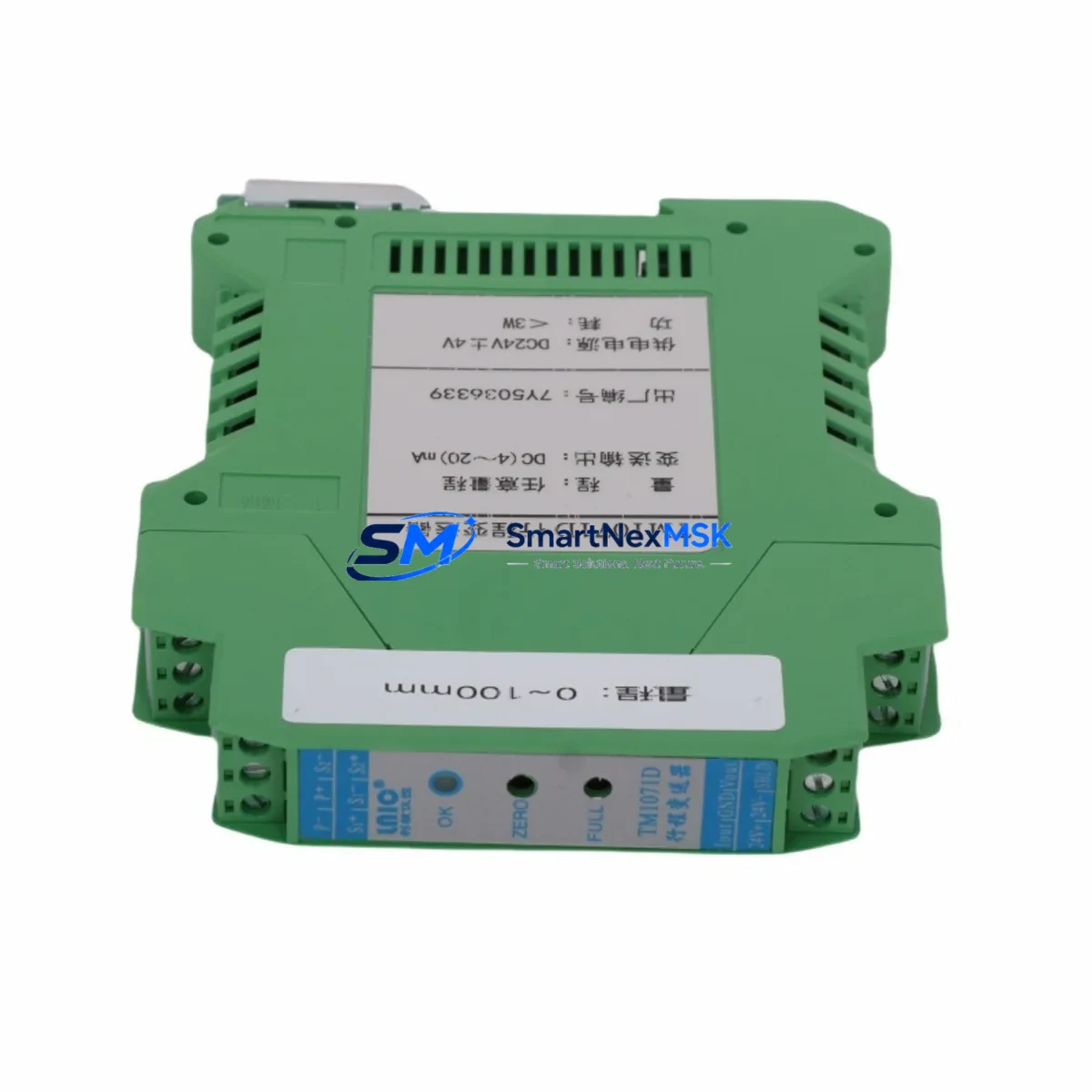
| Output Signal | 4–20 mA (2-wire) | Compatible with standard TM Series analog input cards |
| Supply Voltage | 24 VDC (loop-powered) | Verify existing power supply capacity before installation |
| Stroke / Measurement Range | Per TM1071D datasheet | Confirm stroke matches original sensor specification |
| Terminal Wiring | 2-wire loop, screw terminal | Reuse existing field cable; verify polarity |
| Mounting Interface | Standard flange / rod-end | Check mechanical coupling and alignment with actuator |
| Communication Protocol | Analog 4–20 mA | No protocol migration required; direct drop-in |
| Backplane / Rack Slot | Field-mounted (not rack-based) | No backplane address configuration needed |
| PLC Program Compatibility | Signal-level compatible | Retain existing scaling blocks; verify zero/span calibration |
| HMI Tag Mapping | Unchanged | No HMI screen edits required in standard replacement |
| Commissioning Requirement | Zero/span field calibration | Use existing calibration procedure or LNIC commissioning guide |
| Warranty | 12 Months | Covers manufacturing defects; includes pre-shipment functional test |
Retrofit Planning for Existing Automation Systems
Successful integration of the TM1071D into an operating production environment requires a structured pre-installation review. Begin by auditing the existing control cabinet to confirm the 24 VDC loop power supply — typically sourced from a dedicated LNIC or third-party DIN-rail power supply module — has sufficient current headroom to support the replacement transmitter alongside other active field devices. In multi-drop wiring configurations, verify that the total loop burden does not exceed the analog input card’s rated load resistance.
Next, inspect the terminal block wiring at both the field junction box and the analog input module. The TM1071D uses a standard 2-wire loop connection; in most TM Series installations, the existing field cable can be reused without modification. Label and photograph all terminal connections before disconnecting the original sensor. If the original unit was wired through a signal isolator or surge protection barrier — common in installations near variable frequency drives or high-voltage switchgear — confirm that the TM1071D’s input impedance is compatible with the barrier’s output specification.
At the controller level, locate the analog input channel assigned to the original TM1071D position signal. In TM Series systems, this channel is typically configured within the PLC’s I/O module address map. No address reassignment is required when performing a like-for-like replacement, but engineers should verify the channel’s engineering unit scaling — particularly the zero and full-scale values — against the TM1071D’s calibrated output range. If the original sensor had drifted over time, the replacement unit’s factory calibration may produce a slightly different raw count at the same physical position, requiring a minor span adjustment in the controller’s analog input scaling block.
For facilities running LNIC TM Series HMI panels, the position display faceplate and associated alarm setpoints will remain valid after replacement, provided the new transmitter’s output linearity matches the original. In systems where the position signal feeds a PID loop — for example, controlling a proportional valve or servo actuator — perform a bump test after installation to confirm loop stability before returning the axis to automatic mode.
When the retrofit involves a broader system upgrade — such as migrating from an older TM Series rack to a current-generation LNIC controller platform — additional planning is required. In these scenarios, the TM1071D’s analog output can be wired to a new analog input module on the upgraded rack, with the signal re-scaled in the new program. Engineers should also account for changes in scan time, interrupt handling, and analog filter settings between controller generations, as these can affect position loop response. Related components commonly involved in such migrations include the LNIC TM Series analog input module, the system power supply module, the CPU module, the programming cable for configuration upload and download, and the remote I/O adapter if distributed I/O architecture is retained.
In installations where the TM1071D feeds a motion control or positioning application, verify that the replacement sensor’s mechanical mounting — including the rod-end coupling, clevis pin, and mounting bracket — is correctly aligned and free of side-loading. Misalignment is a leading cause of premature sensor failure and measurement error in linear position applications. LNIC recommends a full mechanical inspection of the actuator and linkage assembly as part of any planned sensor replacement.
Downtime Control During System Migration
Minimizing production downtime during a sensor replacement or broader system migration is a primary concern for industrial maintenance teams. The TM1071D’s drop-in compatibility with TM Series analog input infrastructure means that, in most cases, the physical swap can be completed within a planned maintenance window without requiring controller program changes or HMI modifications.
Before beginning work, export and archive the current PLC program from the host controller using the LNIC programming software. Store the backup on a secure engineering workstation and verify the file integrity before proceeding. This step protects against accidental program loss during power cycling and provides a recovery baseline if commissioning reveals unexpected behavior after the replacement.
During the swap, maintain loop power to non-affected channels to keep other field devices online. Isolate only the channel connected to the TM1071D being replaced. After installing the new unit and restoring wiring, apply loop power and verify the 4–20 mA output at the terminal block using a calibrated loop calibrator before reconnecting to the analog input module. This confirms the transmitter is functional before the controller resumes scanning the channel.
Once the channel is restored, place the affected control loop in manual mode and perform a slow stroke test across the full measurement range. Confirm that the controller’s raw analog count tracks linearly with physical position and that the engineering unit display on the HMI matches the expected value at both endpoints. Only after this verification should the loop be returned to automatic control. Document the commissioning results — including zero count, full-scale count, and any span adjustments made — in the facility’s maintenance management system for future reference.
For planned migrations involving multiple sensors or a full rack replacement, a phased approach is recommended: replace and commission one channel at a time, returning each to automatic control before proceeding to the next. This strategy maintains partial system operation throughout the migration and limits the blast radius of any commissioning issue to a single control loop.
Retrofit Support FAQ
Q1: Is the TM1071D a direct drop-in replacement for the original LNIC TM Series linear position transmitter?
In the majority of standard TM Series installations, yes. The TM1071D maintains the same 4–20 mA output signal, 2-wire loop wiring, and mechanical mounting interface as the original unit. Minor zero/span calibration adjustment at the controller may be required after installation. Customers are advised to confirm the stroke range and supply voltage against their specific installation before ordering.
Q2: What pre-shipment testing is performed on the TM1071D?
Each TM1071D unit undergoes a functional output test prior to shipment, verifying the 4–20 mA signal across the full stroke range. Units are inspected for mechanical integrity, terminal condition, and labeling accuracy. A 12-month warranty covers manufacturing defects from the date of shipment.
Q3: Can the TM1071D be used in a system that has been upgraded from the original TM Series controller to a newer LNIC platform?
Yes. The TM1071D’s standard analog output is compatible with any controller platform that accepts a 4–20 mA input signal. When migrating to a new controller generation, re-scale the analog input channel in the new program to match the TM1071D’s calibrated output range. No hardware modification to the transmitter is required.
Q4: What wiring documentation should I prepare before replacing the original sensor?
Before disconnecting the original unit, photograph and record all terminal connections at the field junction box and the analog input module. Note the channel address, engineering unit scaling values, and any alarm setpoints configured in the controller. If a signal isolator or surge barrier is installed in the loop, record its model number and verify compatibility with the TM1071D’s loop impedance specification. This documentation will accelerate commissioning and serve as a reference for future maintenance.
© 2026 SMARTNEXMSK. All rights reserved.
Original Source: https://smartnexmsk.com
Contact: sales@smartnexmsk.com | +86 18259474341