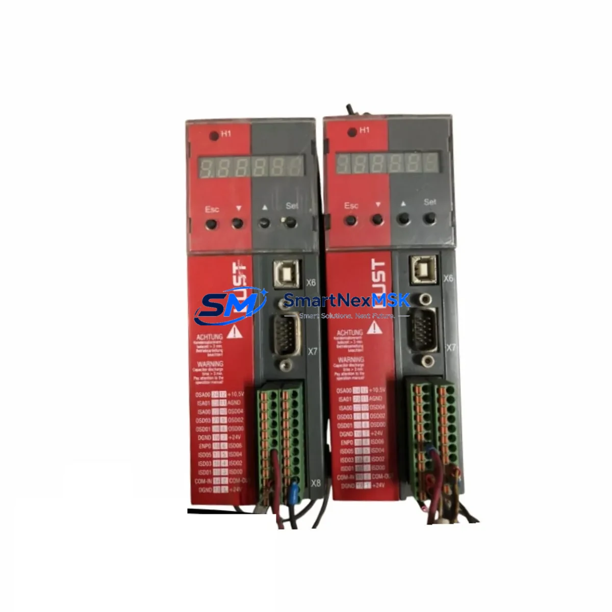
LUST SC34.0300.0011.0000.0-JW1 Retrofit-Ready Control Board for SC34 Series Control Systems
The LUST SC34.0300.0011.0000.0-JW1 is a servo drive control board engineered for direct compatibility with the LUST SC34 series servo drive platform. As legacy SC34 units reach end-of-service life and OEM spare parts become increasingly scarce, this retrofit-ready replacement board provides a reliable, drop-in upgrade path for industrial facilities operating servo-controlled axes in packaging, printing, material handling, and precision motion applications. Whether you are recovering from an unplanned drive failure or executing a planned modernization of an aging control cabinet, the SC34.0300.0011.0000.0-JW1 is stocked, tested, and ready to ship with a 12-month warranty.
Upgrade Compatibility Table
| Parameter | Details |
|---|---|
| SKU / Part Number | SC34.0300.0011.0000.0-JW1 |
| Brand / Manufacturer | LUST Antriebstechnik (Germany) |
| Compatible Series | LUST SC34 Servo Drive Series |
| Module Type | Servo Drive Control Board |
| Mounting / Installation | Direct board-level replacement; matches SC34 drive housing and backplane connector layout |
| Communication Compatibility | Compatible with SC34 series fieldbus interfaces (CANopen, RS-232 diagnostic port) |
| Replacement Recommendation | Suitable for direct substitution of failed or obsolete SC34 control boards; verify firmware revision before commissioning |
| Commissioning Notes | Re-parameterization via LUST CDD+ or DriveManager software recommended after board swap; backup existing drive parameters before replacement |
| Warranty | 12 months from date of shipment; covers manufacturing defects and functional failure under normal operating conditions |
| Country of Origin | Germany |
| Stock Status | In Stock — Ready to Ship |
Retrofit Planning for Existing Automation Systems
Replacing a LUST SC34.0300.0011.0000.0-JW1 control board within an existing servo drive system requires careful pre-planning to ensure a smooth transition with minimal disruption to production. Before removing the failed board, engineers should use the LUST CDD+ commissioning software to export the full parameter set from the drive — including speed loop gains, position controller settings, encoder feedback configuration, and application-specific motion profiles. This parameter backup is critical because the replacement board ships with factory default settings and must be re-commissioned to match the original drive behavior.
In a typical SC34-based control cabinet, the servo drive interfaces with a higher-level controller — commonly a LUST MC6 motion controller or a third-party PLC — via CANopen or a point-to-point serial link. Before the board swap, verify that the node address, baud rate, and CANopen PDO mapping stored in the original drive are documented. After installing the SC34.0300.0011.0000.0-JW1 replacement board, these communication parameters must be restored to ensure the drive is correctly recognized by the master controller without requiring changes to the PLC program or HMI configuration.
Power supply integrity is another critical checkpoint. The SC34 series control board draws its logic supply from the drive’s internal DC bus and auxiliary 24 VDC rail. Before commissioning the replacement board, measure the 24 VDC supply at the control terminal strip to confirm it is within tolerance. A degraded LUST PSU-24 or equivalent 24 V power supply module can cause intermittent control board faults even after a successful hardware replacement. Similarly, inspect the DC bus capacitor bank condition in the SC34 power stage — a weakened capacitor bank can stress the new control board during regenerative braking events.
For systems where the SC34 drive is paired with a LUST resolver-based or incremental encoder feedback module, confirm that the encoder cable shield grounding and differential signal integrity are intact before powering up the replacement board. Encoder signal noise is a common root cause of position feedback errors that can be misdiagnosed as a control board fault. If the system uses a LUST SinCos encoder interface card installed in the drive’s option slot, verify that the option card is reseated correctly after the board replacement procedure.
In multi-axis systems where several SC34 drives share a common DC bus link and a shared LUST braking resistor module, the replacement board commissioning should be performed with the axis isolated from the bus link initially. This allows safe parameter verification and motor identification runs without risk to adjacent drives. Once the axis is confirmed operational in standalone mode, reconnect the DC bus link and verify coordinated motion behavior through the motion controller.
HMI screens that display drive status, fault codes, and axis position data via the LUST MC6 or a third-party SCADA system should be tested after commissioning to confirm that all data tags are updating correctly. In some installations, the HMI reads drive parameters directly via the CANopen object dictionary — if the replacement board firmware version differs from the original, certain object indices may have shifted, requiring a minor HMI tag remapping. Always cross-reference the firmware version of the SC34.0300.0011.0000.0-JW1 against the original drive’s firmware label before finalizing the retrofit.
Downtime Control During System Migration
Minimizing unplanned downtime during a LUST SC34 control board replacement begins with preparation before the machine is taken offline. The most effective strategy is to pre-stage the SC34.0300.0011.0000.0-JW1 replacement board alongside a printed copy of the original drive’s parameter report, the wiring diagram for the control terminal strip, and the CANopen node configuration sheet. With these documents in hand, an experienced commissioning engineer can complete the physical board swap, parameter restore, and functional test in under two hours for a single-axis application.
For multi-axis lines where the SC34 drives are networked via CANopen and coordinated by a LUST MC6 motion controller, a phased replacement approach is recommended. Replace and commission one axis at a time while keeping the remaining axes in a safe hold state. This prevents a full line stoppage and allows production to resume on unaffected axes while the retrofit is in progress. The MC6 motion controller supports axis-level enable/disable commands that can be used to isolate the axis under service without modifying the PLC program or disrupting the fieldbus network.
Before powering down the drive for board replacement, capture a live oscilloscope trace of the encoder feedback signals and the current loop response if possible. This baseline data serves as a commissioning reference after the replacement board is installed and allows rapid identification of any tuning deviations introduced by component tolerances between the old and new boards. In most cases, the original PID parameters transfer directly without retuning, but having the baseline trace eliminates guesswork during the post-replacement functional test.
All replacement boards shipped by SMARTNEXMSK undergo a pre-shipment functional test that verifies power-on self-test completion, communication port integrity, and basic I/O response. This factory-level verification reduces the risk of receiving a non-functional board and helps ensure that the first power-up on site proceeds without hardware-related surprises. Combined with the 12-month warranty coverage, this testing protocol supports a confident, low-risk retrofit execution.
Retrofit Support FAQ
Q1: Is the SC34.0300.0011.0000.0-JW1 a direct drop-in replacement for my existing LUST SC34 control board?
In the majority of SC34 series applications, yes. The SC34.0300.0011.0000.0-JW1 matches the original board’s connector layout, mounting points, and electrical interface. However, we recommend confirming the drive’s full model number and hardware revision before ordering to ensure full compatibility. Our technical team can assist with cross-referencing your existing board’s label against the replacement part.
Q2: Do I need to re-wire the control terminal strip when installing the replacement board?
No re-wiring is required in standard replacement scenarios. The SC34.0300.0011.0000.0-JW1 uses the same terminal strip pinout as the original SC34 control board. Document the existing wiring with photographs before removal, and reconnect to the same terminal positions on the replacement board. Pay particular attention to the enable input, fault reset, and analog reference signal terminals, as incorrect connections on these signals can prevent the drive from enabling after commissioning.
Q3: What commissioning steps are required after installing the replacement board?
After physical installation, restore the backed-up parameter set using LUST CDD+ or DriveManager software. Verify the CANopen node address, baud rate, and PDO configuration match the original settings. Perform a motor identification run if the drive’s motor data parameters were not fully backed up. Conduct a low-speed jog test to confirm encoder feedback direction and scaling before enabling full-speed operation. Check all fault and warning outputs for correct function before returning the axis to automatic mode.
Q4: What does the 12-month warranty cover, and what is the return process if the board is faulty?
The 12-month warranty covers manufacturing defects and functional failures under normal operating conditions from the date of shipment. It does not cover damage caused by incorrect installation, overvoltage events, or environmental contamination. If you receive a board that fails during the warranty period, contact sales@smartnexmsk.com with your order number and a description of the fault. Our team will arrange a replacement shipment or technical support to resolve the issue promptly.
© 2026 SMARTNEXMSK. All rights reserved.
Original Source: https://smartnexmsk.com
Contact: sales@smartnexmsk.com | +86 18259474341