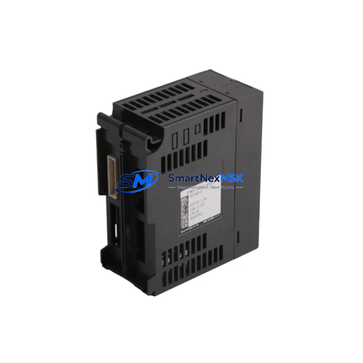
M-SYSTEM R3-PS3-R Retrofit-Ready Power Supply for R3 Series Control Systems
The M-SYSTEM R3-PS3-R is a dedicated power supply module engineered for the M-SYSTEM R3 Series Remote I/O platform — one of the most widely deployed distributed I/O architectures in process automation, chemical plants, and utility control systems across Asia and beyond. As legacy installations age and original spare parts become increasingly difficult to source, the R3-PS3-R has become a critical retrofit component for engineers tasked with keeping aging control infrastructure operational without full system replacement.
Whether you are replacing a failed unit in an existing R3 rack, upgrading power capacity during a control cabinet modernization, or migrating from an older R3-PS2 or R3-PS1 power supply variant, the R3-PS3-R provides a reliable, specification-matched solution that minimizes engineering rework and commissioning time. It is designed to slot directly into the standard R3 base unit backplane, maintaining full compatibility with the R3-series module addressing scheme and field wiring terminal layout.
For procurement teams managing aging plant assets, the R3-PS3-R represents a cost-effective alternative to full platform migration. Rather than replacing an entire R3 rack assembly — including all installed I/O modules, field wiring, and associated DCS configuration — a targeted power supply replacement restores system reliability at a fraction of the cost and schedule impact. SMARTNEXMSK maintains verified inventory of the R3-PS3-R and ships with a functional test certificate and 12-month warranty from date of dispatch.
Upgrade Compatibility Table
| Parameter | R3-PS3-R Specification | Retrofit Notes |
|---|---|---|
| Input Voltage | 100–240 VAC, 50/60 Hz | Verify existing cabinet supply voltage before installation |
| Output Voltage | 24 VDC (regulated) | Confirm downstream module power requirements match 24 VDC rail |
| Backplane Interface | R3 Series standard backplane connector | Direct drop-in for R3-PS1 / R3-PS2 positions; no adapter required |
| Terminal Wiring | Screw-type terminal block | Re-use existing field wiring; verify torque spec per M-SYSTEM manual |
| Module Address | Fixed slot assignment (no DIP switch) | No address reconfiguration required after swap |
| Communication Compatibility | Passive power supply — no protocol dependency | Compatible with HART, Modbus RTU, and FOUNDATION Fieldbus R3 I/O modules on same rack |
| Replacement Models | R3-PS1, R3-PS2 (older variants) | Confirm output current rating upgrade is within cabinet thermal budget |
| Commissioning | Power-on self-test via LED indicators | Verify green PWR LED and absence of fault LED before returning to service |
| Warranty | 12 Months | Covered from date of shipment; includes functional test certificate |
Retrofit Planning for Existing Automation Systems
Successful integration of the R3-PS3-R into an existing control system begins well before the physical swap. Engineers should start by auditing the total power consumption of all modules currently installed on the affected R3 base unit — including analog input modules such as the R3-DA16, thermocouple input modules like the R3-TS8, and any digital output modules such as the R3-YV8. The aggregate current draw must remain within the R3-PS3-R’s rated output capacity to avoid nuisance tripping or thermal stress on the new supply.
For systems that include communication modules — for example, the R3-NE1 Ethernet interface module or the R3-RS4 serial communication module — it is important to confirm that the power rail remains stable during module initialization sequences, which can produce brief inrush current spikes. In multi-rack configurations where an R3-EX expansion base unit is connected via the R3 expansion cable, the power budget calculation must account for the expansion rack’s independent supply as well.
Terminal wiring should be documented with photographs before disconnection. The R3-PS3-R uses the same screw-type terminal block pitch as its predecessors, so existing field cables can typically be reconnected without modification. However, engineers should inspect insulation condition and re-torque all terminals to the values specified in the M-SYSTEM R3 Series hardware manual. If the control cabinet also houses an R3-SV4 signal conditioner or an R3-PA4 pulse input module, these should be powered down in a controlled sequence before the power supply is removed to prevent data corruption in connected DCS or SCADA historian systems.
Where the R3 rack interfaces with an HMI — such as a panel-mounted operator station running M-SYSTEM’s configuration software or a third-party SCADA via OPC — the HMI communication link should be placed in manual or bypass mode prior to the swap. This prevents false alarms from propagating to the control room during the brief power interruption. After the R3-PS3-R is installed and powered on, the HMI connection should be restored and all I/O channel values verified against known reference readings before returning the loop to automatic control.
Downtime Control During System Migration
Minimizing unplanned downtime is the primary concern for any retrofit involving a power supply module in a live production environment. The recommended approach is to schedule the R3-PS3-R swap during a planned maintenance window, even if the window is as short as 15–30 minutes. Before the outage begins, export the current I/O configuration from the R3 system using M-SYSTEM’s configuration utility and save a backup of the rack parameter file. This ensures that if any module — such as an R3-YS8 analog output module or an R3-CT4 current transformer input module — loses its configuration during the power cycle, it can be restored from the backup without manual re-entry.
During the swap, keep the replacement R3-PS3-R in its anti-static packaging until the moment of installation. Inspect the backplane connector pins on both the module and the base unit for contamination or mechanical damage before seating the module. Once installed, apply power and observe the LED status indicators: a steady green PWR LED with no fault indication confirms normal operation. Do not return the system to automatic control until all I/O channels have been scanned and verified — this typically takes less than two minutes on a standard R3 rack with 16 or fewer I/O slots.
For critical processes where even a brief interruption is unacceptable, consider pre-staging a fully configured spare R3 base unit with the R3-PS3-R already installed and tested. This hot-swap preparation strategy reduces field replacement time to under five minutes and eliminates the risk of installation errors under time pressure. All units shipped by SMARTNEXMSK are functionally tested prior to dispatch and include a test certificate, supporting rapid deployment with confidence.
Retrofit Support FAQ
Q1: Is the R3-PS3-R a direct replacement for the R3-PS2 and R3-PS1?
Yes. The R3-PS3-R is mechanically and electrically compatible with the same backplane slot positions used by the R3-PS1 and R3-PS2. No adapter plate or wiring modification is required. Confirm that the output current rating of the R3-PS3-R meets or exceeds the total load of all modules installed on the rack before completing the swap.
Q2: What pre-shipment testing is performed on the R3-PS3-R?
Every R3-PS3-R unit supplied by SMARTNEXMSK undergoes a full functional test including input voltage range verification, output voltage regulation check, and LED status confirmation under load. A test certificate is included with each shipment. The unit is covered by a 12-month warranty from the date of shipment.
Q3: How do I verify wiring compatibility before installation?
The R3-PS3-R uses the same screw-type terminal block layout as previous R3 Series power supply variants. Cross-reference the terminal designations in the M-SYSTEM R3 Series hardware manual against your existing field wiring documentation. In most cases, existing cables can be reconnected directly. Re-torque all terminals after reconnection and perform an insulation resistance check if the wiring has been in service for more than five years.
Q4: Can the R3-PS3-R support a rack that includes both HART and Modbus RTU I/O modules simultaneously?
Yes. The R3-PS3-R is a passive power supply and has no dependency on the communication protocol used by the I/O modules it powers. It will support any combination of HART-enabled analog modules, Modbus RTU communication modules, and standard digital I/O modules installed in the same R3 base unit, provided the total current draw remains within the rated output capacity.
© 2026 SMARTNEXMSK. All rights reserved.
Original Source: https://smartnexmsk.com
Contact: sales@smartnexmsk.com | +86 18259474341