M2I XTOP07TW-UD Retrofit-Ready HMI for XTOP Control Systems
The M2I XTOP07TW-UD is a 7-inch TFT widescreen HMI touch panel engineered for seamless integration into existing XTOP Series control architectures. As legacy HMI panels reach end-of-life or become unavailable through standard distribution channels, the XTOP07TW-UD provides a verified drop-in retrofit path that preserves existing wiring layouts, communication protocols, and operator screen logic — minimizing engineering rework and unplanned downtime during system modernization.
Designed for industrial environments where control continuity is non-negotiable, the XTOP07TW-UD supports the full range of M2I XDesignerPlus project files, allowing engineers to migrate or reuse existing HMI screen projects without rebuilding from scratch. Its compatibility with RS-232, RS-422, RS-485, and Ethernet communication interfaces makes it a practical replacement candidate across a wide spectrum of PLC platforms and fieldbus topologies commonly found in legacy automation cabinets.
Whether you are upgrading a single operator station or modernizing an entire production line’s control infrastructure, the XTOP07TW-UD delivers the display resolution, touch accuracy, and protocol flexibility required to maintain operational integrity throughout the transition. Units are pre-tested prior to shipment, backed by a 12-month warranty, and available from verified stock in Xiamen for rapid global dispatch.
Upgrade Compatibility Table
| Parameter | Detail |
|---|---|
| SKU | XTOP07TW-UD |
| Brand / Series | M2I / XTOP Series |
| Display | 7-inch TFT Widescreen, 800×480 resolution |
| Touch Type | Resistive touch panel |
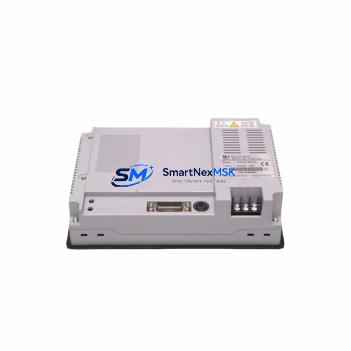
| Communication Ports | RS-232, RS-422, RS-485, USB Host/Slave, Ethernet (RJ45) |
| Power Supply | DC 24V (±10%), verify existing cabinet PSU capacity before installation |
| Panel Cutout | Compatible with standard XTOP07 series cutout dimensions — verify against existing bezel |
| Software Compatibility | M2I XDesignerPlus — existing project files (.xpd) are directly importable |
| PLC Compatibility | Mitsubishi, Siemens, Omron, LS Electric, Delta, Schneider, and 300+ driver library |
| Replacement Recommendation | Direct retrofit for XTOP07TW-UD and adjacent XTOP Series discontinued models |
| Commissioning Notes | Verify COM port address assignment, baud rate, and station number before power-on |
| Warranty | 12 months from date of shipment |
| Origin | Republic of Korea (KR) |
Retrofit Planning for Existing Automation Systems
A successful XTOP07TW-UD retrofit begins well before the panel arrives on-site. Engineers should audit the existing control cabinet to confirm that the 24VDC power supply — often an M2I or third-party DIN-rail PSU — can sustain the HMI’s operating current draw alongside other active loads such as relay output modules, communication gateways, and indicator circuits. In cabinets where the original HMI was powered from a shared rail with I/O expansion modules or a CPU rack backplane, a dedicated power branch is recommended to prevent voltage sag during display backlight startup.
Terminal wiring for the RS-485 communication link should be inspected and re-terminated if the existing cable run exceeds recommended lengths or shows signs of insulation degradation. The XTOP07TW-UD’s COM2 port supports RS-485 multi-drop configurations, which is particularly relevant in systems where the HMI communicates with a LS Electric XGB or XGI series PLC controller over a shared bus alongside remote I/O stations. Confirm the termination resistor is correctly placed at the physical end of the bus, not at an intermediate node.
For systems that previously relied on a dedicated programming cable — such as the M2I USB-to-serial download cable — verify that the replacement unit’s USB slave port is recognized by the engineering workstation running XDesignerPlus. In some Windows 10/11 environments, a driver update may be required before the first project download. It is advisable to perform a full project compile and simulation on the engineering PC before connecting to the live panel.
Where the original system included a communication module bridging the HMI to a Profibus DP or DeviceNet network — for example, a gateway module mounted in the same control cabinet — confirm that the XTOP07TW-UD’s Ethernet port can serve as an alternative communication path using the Modbus TCP driver, potentially eliminating the need for the legacy fieldbus adapter entirely. This simplification reduces component count and future maintenance overhead.
In multi-panel installations, where the XTOP07TW-UD replaces one station in a network of HMI terminals sharing a common PLC data source, verify that the station address (node number) assigned in XDesignerPlus matches the address previously held by the retired unit. Duplicate station addresses on an RS-485 bus will cause communication collisions and unpredictable screen behavior. After address confirmation, perform a live data read test on all monitored tags — including analog input values from connected I/O modules, motor run/stop status bits, and alarm register states — before returning the line to production.
Panels being installed as part of a broader control cabinet upgrade — for instance, alongside a new DIN-rail mounted CPU module, updated output relay cards, or a replacement Ethernet switch for plant network connectivity — should be commissioned in sequence: power supply verification first, PLC communication second, HMI screen validation third. This staged approach isolates fault sources and accelerates the overall commissioning timeline.
Downtime Control During System Migration
Minimizing production interruption during an HMI retrofit requires a structured pre-outage preparation protocol. Before the scheduled maintenance window, the existing XTOP07TW-UD project file should be backed up from the panel using XDesignerPlus’s upload function and archived alongside the PLC program backup — typically exported from the connected controller’s programming software. This dual backup ensures that if any issue arises during commissioning, the original control logic and screen configuration can be restored within minutes rather than hours.
During the physical swap, the panel cutout dimensions of the XTOP07TW-UD allow direct replacement without cabinet door modification in most standard enclosure configurations. Label all terminal connections before disconnection, photograph the existing wiring layout, and use the terminal block labeling as a reference during reconnection. If the original installation used a dedicated communication cable routed through cable trays to a remote PLC rack, retain that cable and simply re-terminate at the new panel’s COM port.
Once the replacement panel is physically installed and powered, the pre-loaded project file should be downloaded via USB before enabling PLC communication. Verify that all screen pages render correctly in offline simulation mode, then enable the communication driver and confirm live data exchange with the connected controller. Monitor the first 15–30 minutes of operation for any communication timeout alarms or unexpected screen transitions before releasing the system to operators. With proper preparation, total outage time for a single-panel replacement can typically be contained to under two hours.
Retrofit Support FAQ
Q1: Is the XTOP07TW-UD a direct drop-in replacement for the original XTOP07TW-UD panel?
Yes. The XTOP07TW-UD is the same model designation and maintains identical panel cutout dimensions, communication port layout, and software compatibility with XDesignerPlus project files. Existing screen projects can be uploaded from the old panel (if still functional) or downloaded from backup and transferred directly to the replacement unit without modification in most cases.
Q2: What commissioning steps are required after installation?
After physical installation and wiring, download the project file via USB, verify COM port settings (baud rate, data bits, parity, stop bits, station number) match the connected PLC’s configuration, enable the communication driver, and perform a live tag read test across all monitored data points. Check alarm history registers and confirm that any interlock logic dependent on HMI tag writes functions correctly before returning to production.
Q3: Can the XTOP07TW-UD communicate with PLCs from brands other than M2I?
Yes. The XDesignerPlus driver library supports over 300 PLC and controller types, including Mitsubishi MELSEC Q/L/FX series, Siemens S7-200/300/400/1200/1500, Omron CJ/CS/NJ series, Delta DVP and AS series, Schneider Modicon M340/M580, and LS Electric XGB/XGI series, among others. Select the appropriate driver during project configuration and verify the communication parameters against the PLC’s port settings.
Q4: What does the 12-month warranty cover, and what pre-shipment testing is performed?
Each XTOP07TW-UD unit undergoes functional power-on testing, display verification, touch calibration check, and communication port continuity testing prior to shipment. The 12-month warranty covers manufacturing defects and component failures under normal operating conditions. Units showing physical damage from incorrect installation, overvoltage, or environmental exposure outside rated specifications are excluded. Warranty claims are processed through SMARTNEXMSK with replacement or repair turnaround coordinated to minimize customer downtime.
© 2026 SMARTNEXMSK. All rights reserved.
Original Source: https://smartnexmsk.com
Contact: sales@smartnexmsk.com | +86 18259474341