MAIWE MIEF1203-P-SC-2-A220-V5.0 Maintenance-Ready Spare for MIEF1203 Automation
The MAIWE MIEF1203-P-SC-2-A220-V5.0 is an original fiber optic interface module engineered for industrial automation networks where signal integrity and long-distance transmission reliability are non-negotiable. Designed for the MIEF1203 series, this module supports SC single-mode fiber at an extended reach of 220 km, making it a critical spare for backbone communication links in DCS, SCADA, and PLC-based control architectures. For maintenance engineers managing aging control systems or executing planned shutdowns, having a verified, tested replacement on the shelf is the single most effective strategy to minimize unplanned downtime and protect production continuity.
At SMARTNEXMSK, every MIEF1203-P-SC-2-A220-V5.0 unit is sourced from authorized supply channels, inspected against original MAIWE specifications, and tested prior to shipment. Each unit ships with a 12-month warranty and full traceability documentation, giving procurement engineers the confidence to stock this module as a long-term spare without lifecycle risk.
Spare Maintenance Table
| Parameter | Specification |
|---|---|
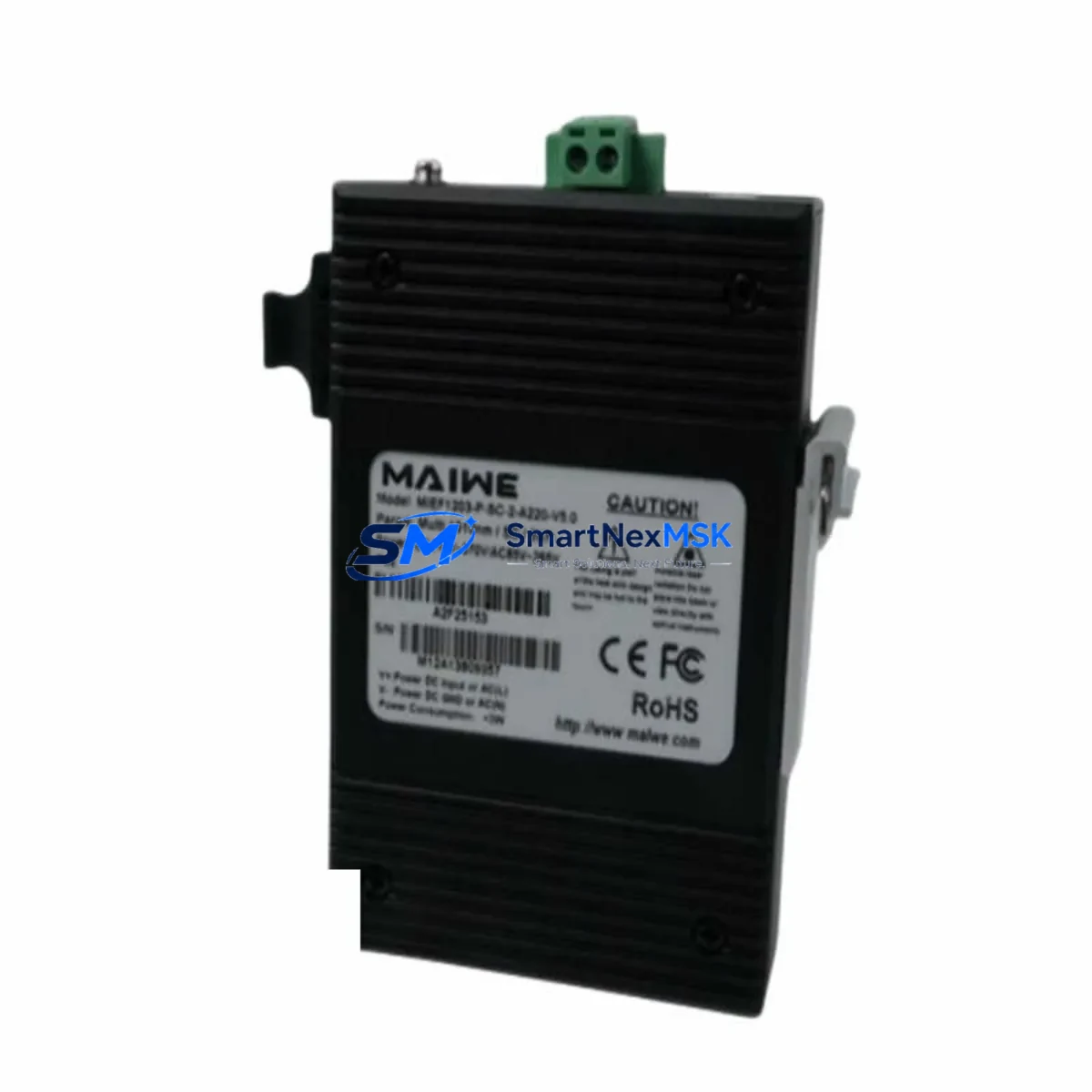
| Part Number / SKU | MIEF1203-P-SC-2-A220-V5.0 |
| Brand | MAIWE |
| Series | MIEF1203 |
| Module Type | Fiber Optic Interface Module |
| Fiber Connector | SC (Single-Mode) |
| Transmission Distance | Up to 220 km |
| Port Count | 2-port configuration |
| Firmware Version | V5.0 |
| Power Supply | 220 VAC (A220 variant) |
| Origin | China (CN) |
| Application Environment | Industrial automation, DCS, SCADA, PLC backbone networks |
| Installation | Panel-mount / rack-mount per MIEF1203 chassis standard |
| Operating Temperature | -20°C to +70°C (industrial grade) |
| Maintenance Recommendation | Inspect fiber connectors and SC ports every 6 months; clean with IEC 61300-3-35 compliant tools |
| Warranty | 12 Months — covers manufacturing defects and functional failure under normal operating conditions |
| Compatibility | MIEF1203 series chassis; compatible with MAIWE industrial fiber optic network platforms |
Maintenance Planning for Continuous Operation
When a fiber optic interface module such as the MIEF1203-P-SC-2-A220-V5.0 is flagged for replacement during a scheduled inspection or emergency fault isolation, experienced maintenance engineers know that the module itself is rarely the only component requiring attention. A thorough site assessment should accompany every fiber module swap.
Begin by verifying the 220 VAC power supply feeding the MIEF1203 chassis — power fluctuations or inadequate surge protection are a leading cause of premature module failure. Check the associated power supply module (PSU) for output voltage stability and inspect the terminal blocks and wiring harness connected to the chassis backplane for signs of oxidation, loose terminations, or insulation degradation.
On the communication side, inspect the SC fiber patch cables and fiber splice points along the 220 km link. Dirty or damaged SC connectors are a frequent source of signal attenuation that can be misdiagnosed as module failure. Optical power meters should be used to verify link budget before and after module replacement. If the MIEF1203 chassis hosts additional fiber ports or redundant links, inspect companion fiber optic modules in the same rack for consistent optical performance.
For systems integrating the MIEF1203-P-SC-2-A220-V5.0 into a broader DCS or PLC architecture, also review the I/O modules and communication cards interfacing with the fiber backbone. Signal isolators between the fiber network and field I/O loops should be tested for drift, particularly in high-EMI environments. Relay output modules connected downstream of the communication link should be checked for contact wear and coil resistance.
HMI panels and SCADA workstations receiving data over the MIEF1203 fiber link should be monitored for communication timeout errors during the replacement window — these logs often reveal intermittent faults that predate the module failure. If the system uses a managed industrial Ethernet switch or media converter in conjunction with the MIEF1203 module, inspect those devices for port errors and firmware currency.
Finally, review the fuse and circuit protection inventory for the control cabinet. Blown fuses or tripped breakers associated with the fiber module’s power circuit are a common secondary finding during unplanned outages. Stocking spare fuses, terminal blocks, and SC fiber patch cables alongside the MIEF1203-P-SC-2-A220-V5.0 module itself is a best practice that reduces mean time to repair (MTTR) significantly.
Site Replacement Workflow
Step 1 — Pre-Replacement Verification: Confirm the replacement unit SKU (MIEF1203-P-SC-2-A220-V5.0) matches the installed module label exactly, including firmware version V5.0 and power variant A220. Cross-reference with the system’s as-built documentation or cabinet BOM.
Step 2 — Safe Isolation: Follow site LOTO (Lockout/Tagout) procedures. De-energize the MIEF1203 chassis power supply before removing the module. Do not hot-swap unless the chassis documentation explicitly supports it.
Step 3 — Fiber Disconnection: Label and photograph SC fiber connections before removal. Clean SC connectors on both the cable and the new module using an approved fiber optic cleaning tool before reconnection.
Step 4 — Module Swap: Seat the replacement MIEF1203-P-SC-2-A220-V5.0 firmly into the chassis slot. Verify chassis backplane connector engagement. Re-energize and observe module status LEDs for normal link indication.
Step 5 — Link Verification: Use an optical power meter to confirm received optical power is within the module’s specified sensitivity range. Check SCADA/HMI for restored communication and clear any latched alarms.
Step 6 — Documentation: Record the replacement in the site maintenance log with date, technician ID, old module serial number, and new module serial number. Update the spare parts inventory to trigger reorder of a replacement unit.
This workflow is applicable whether replacing a failed module in an emergency or executing a proactive swap during a planned maintenance window. The MIEF1203-P-SC-2-A220-V5.0’s compatibility with the MIEF1203 series chassis ensures no configuration changes are required in most installations, significantly reducing commissioning time and the risk of parameter errors during restart.
Spare Parts Support FAQ
Q1: What is the shelf life and storage recommendation for the MIEF1203-P-SC-2-A220-V5.0 as a stocked spare?
The module can be stored for up to 5 years in a dry, ESD-protected environment at temperatures between -20°C and +70°C. Store in the original anti-static packaging with desiccant. Inspect SC connector caps and verify firmware version label integrity annually. SMARTNEXMSK recommends stocking at least one unit per critical fiber link in your control system.
Q2: How do I verify compatibility before installation if my existing module label is worn or missing?
Cross-reference the chassis model number (MIEF1203 series) and the power supply variant (A220 = 220 VAC input) with your cabinet’s electrical drawings. The V5.0 firmware designation is backward-compatible with earlier MIEF1203 chassis revisions in most configurations. Contact SMARTNEXMSK with your system’s as-built documentation for a compatibility confirmation before ordering if uncertain.
Q3: What pre-shipment testing does SMARTNEXMSK perform on this module?
Each MIEF1203-P-SC-2-A220-V5.0 unit undergoes power-on functional testing, optical port verification, and firmware version confirmation prior to shipment. Units are packed in ESD-safe materials with individual inspection records. The 12-month warranty covers manufacturing defects and functional failure under normal operating conditions from the date of shipment.
Q4: Can this module replace older MIEF1203 variants with different firmware versions?
In most cases, yes — the MIEF1203-P-SC-2-A220-V5.0 (V5.0 firmware) is designed as a drop-in replacement for earlier MIEF1203-P-SC-2-A220 variants. However, if your system uses version-locked firmware or proprietary configuration files tied to an earlier firmware revision, consult your DCS/SCADA vendor’s compatibility matrix or contact SMARTNEXMSK’s technical team for guidance before proceeding with the swap.
© 2026 SMARTNEXMSK. All rights reserved.
Original Source: https://smartnexmsk.com
Contact: sales@smartnexmsk.com | +86 18259474341