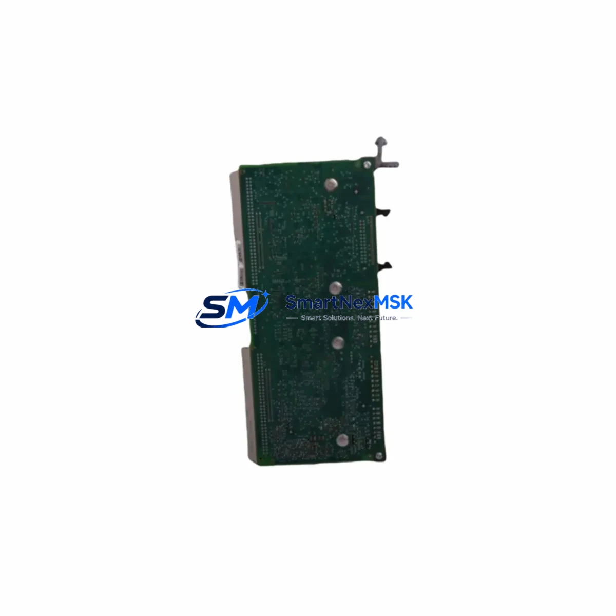
MELTAL MT1102-02-00 Spare for MT/MS Series Automation: Precision Spare Parts for Industrial Downtime Control
The MELTAL MT1102-02-00 is an original PLC control unit designed for deployment within the MT and MS series automation architecture. As a maintenance-ready spare, this module is engineered to support rapid field replacement, minimize unplanned downtime, and sustain continuous operation in demanding industrial environments. Whether you are managing a scheduled overhaul, responding to an emergency fault, or building a proactive spare parts inventory, the MT1102-02-00 delivers the compatibility, reliability, and traceability that maintenance and procurement engineers require.
Sourced directly from authorized supply channels, each unit undergoes pre-shipment functional verification to confirm electrical integrity and firmware compatibility before dispatch. With a 12-month warranty and documented test records, this spare part is suitable for critical control cabinet applications across manufacturing, process automation, energy, and infrastructure sectors.
Spare Maintenance Table
| Parameter | Specification |
|---|---|
| Part Number / SKU | MT1102-02-00 |
| Brand | MELTAL |
| Series Compatibility | MT Series / MS Series PLC Platforms |
| Module Type | PLC Control Unit |
| Compatible Expansion Modules | MS3101-00-00, MS3102-01-00 |
| Mounting | DIN Rail / Panel Mount (per MT/MS series standard) |
| Operating Voltage | 24 VDC nominal (per MT series specification) |
| Operating Temperature | 0°C to +55°C (standard industrial range) |
| Protection Rating | IP20 (control cabinet installation) |
| Country of Origin | China |
| Weight | 740 g |
| Pre-Shipment Test | Functional verification completed |
| Warranty | 12 Months from date of shipment |
| Lead Time | In-stock units ship within 1–3 business days |
| Application Environment | Industrial automation, process control, discrete manufacturing |
Maintenance Planning for Continuous Operation
When replacing the MT1102-02-00 control unit in a live MT/MS series control cabinet, a disciplined maintenance workflow requires more than a direct module swap. Maintenance engineers should treat this replacement as an opportunity to audit the surrounding electrical and control infrastructure to prevent secondary failures and extend system service life.
Begin by inspecting the 24 VDC power supply module feeding the PLC rack. Aging or undersized power supplies are a leading cause of control unit instability and should be load-tested before the new MT1102-02-00 is commissioned. Simultaneously, verify the condition of the MS3101-00-00 digital input expansion module and the MS3102-01-00 digital output expansion module — both are integral to the MT/MS I/O architecture and should be checked for contact wear, terminal oxidation, and firmware version alignment with the replacement control unit.
Inspect all terminal blocks and DIN rail wiring harnesses within the cabinet. Loose or corroded field wiring connections are frequently the root cause of intermittent faults that are misdiagnosed as control unit failures. Pay particular attention to the 24 VDC common rail and field ground bonding to ensure signal integrity across the I/O bus.
For systems with active communications, validate the RS-485 or Ethernet communication module connected to the MT1102-02-00. Communication timeouts and CRC errors often indicate cable degradation or termination resistance drift rather than a failed control unit. If the system uses a signal isolator or surge protection module on the communication line, inspect it for thermal discoloration or dielectric breakdown.
Procurement engineers building a spare parts kit around the MT1102-02-00 should also stock the associated backup battery or supercapacitor retention module used for program memory retention during power loss events. Additionally, consider maintaining a buffer stock of blade-type or cylindrical fuses rated for the MT series power distribution circuit, as these are consumable protection components that are often overlooked until a fault event occurs.
For facilities operating legacy MT/MS installations beyond their original design life, the MT1102-02-00 serves as a direct-fit replacement that avoids costly system redesign. Pairing this control unit with a refreshed HMI operator panel compatible with the MT series communication protocol can further extend system usability without requiring a full platform migration.
Site Replacement Workflow
Step 1 — Pre-Replacement Verification: Confirm the installed unit’s part number against the MT1102-02-00 label and cross-reference with the cabinet wiring diagram. Download or photograph the existing PLC program and parameter configuration before powering down.
Step 2 — Safe Isolation: Isolate the control cabinet from mains supply using the appropriate lockout/tagout procedure. Discharge any residual capacitance in the power supply rail before handling the control unit.
Step 3 — Module Removal: Release the DIN rail locking tab and disconnect all field wiring connectors in labeled sequence. Remove the MT1102-02-00 from the rack, noting the slot position for reinstallation reference.
Step 4 — Replacement Installation: Seat the new MT1102-02-00 onto the DIN rail and reconnect all field wiring connectors in reverse sequence. Verify terminal torque values per the MT series installation manual.
Step 5 — Program Restore and Commissioning: Restore the PLC program and parameter set. Power up the system and perform a full I/O scan to confirm all digital inputs, digital outputs, and communication links are operating correctly before returning the system to production.
This workflow is designed to minimize mean time to repair (MTTR) and ensure that the replacement MT1102-02-00 is commissioned with the same configuration as the failed unit, preserving system compatibility and reducing the risk of commissioning errors.
Spare Parts Support FAQ
Q1: Is the MT1102-02-00 a direct replacement for the original installed unit without firmware modification?
In most MT/MS series installations, the MT1102-02-00 is a direct hardware replacement. However, if the installed system firmware version differs from the replacement unit’s factory firmware, a firmware update or parameter re-upload may be required. We recommend confirming the firmware revision of the installed unit prior to ordering and contacting our technical team if version alignment support is needed.
Q2: What does the 12-month warranty cover, and how is a warranty claim initiated?
The 12-month warranty covers manufacturing defects, functional failures under normal operating conditions, and pre-shipment test discrepancies. Warranty claims are initiated by contacting sales@smartnexmsk.com with the order reference, failure description, and photographic evidence. Replacement or repair is processed within the agreed lead time upon fault confirmation.
Q3: Can this spare part be held in long-term storage as part of a critical spares inventory?
Yes. The MT1102-02-00 is suitable for long-term storage when kept in its original anti-static packaging in a dry, temperature-controlled environment (recommended: 10°C to 40°C, relative humidity below 75% non-condensing). For storage periods exceeding 24 months, a pre-commissioning functional test is recommended before installation.
Q4: How is compatibility with the existing MT/MS series system verified before shipment?
Each MT1102-02-00 unit is cross-referenced against the declared system series and expansion module configuration (including MS3101-00-00 and MS3102-01-00) prior to dispatch. Our technical team can assist with compatibility verification based on your cabinet wiring diagram, existing part numbers, or system nameplate data. Contact us at sales@smartnexmsk.com or +86 18259474341 before placing your order if you require pre-sale compatibility confirmation.
© 2026 SMARTNEXMSK. All rights reserved.
Original Source: https://smartnexmsk.com
Contact: sales@smartnexmsk.com | +86 18259474341