MOLAND 203133-512B Maintenance-Ready Spare for 203133 Series Automation
The MOLAND 203133-512B is a critical spare part for industrial automation systems built on the 203133 Series platform. Designed for maintenance engineers and procurement teams managing aging control infrastructure, this original PLC control board enables rapid fault isolation and system restoration with minimal downtime. Whether you are executing a planned shutdown inspection, responding to an unplanned trip, or building a strategic spare parts inventory for a legacy control cabinet, the 203133-512B delivers the compatibility, reliability, and traceability required in demanding industrial environments.
Industrial facilities operating continuous processes — including chemical plants, power generation stations, water treatment facilities, and discrete manufacturing lines — cannot afford extended downtime caused by unavailable spare parts. The 203133-512B is stocked and tested to support emergency replacement scenarios, with each unit verified for electrical integrity and functional performance prior to shipment. A 12-month warranty is included with every order, providing procurement engineers with the confidence needed to justify spare parts investment to maintenance management.
Spare Maintenance Table
| Parameter | Specification |
|---|---|
| Part Number | 203133-512B |
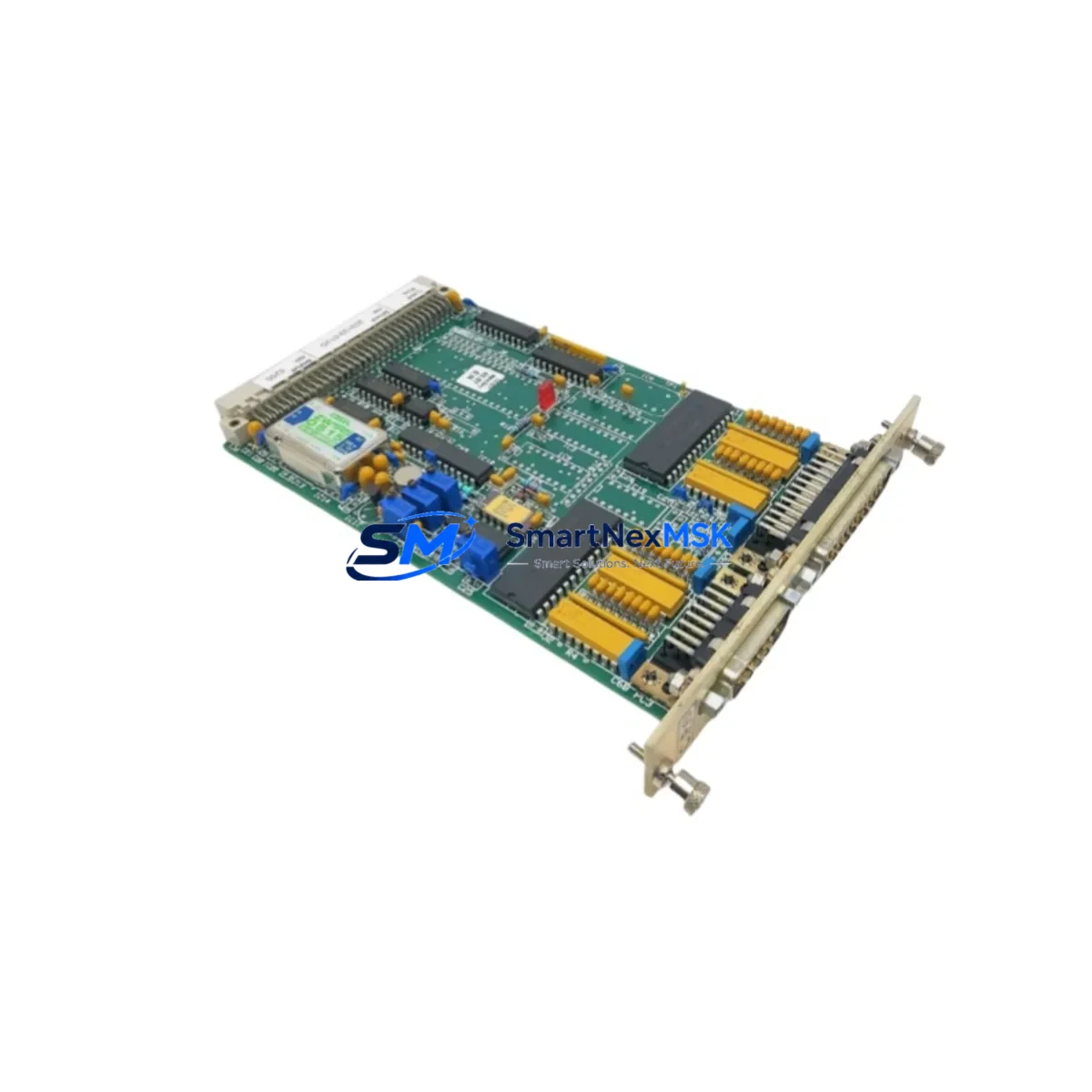
| Brand | MOLAND |
| Series | 203133 Series |
| Product Type | PLC Control Board |
| Origin | China (CN) |
| Compatibility | 203133 Series automation systems; legacy PLC control cabinets |
| Application Environment | Industrial automation, DCS/PLC control panels, process control |
| Installation | Direct board-level replacement; refer to OEM documentation for slot assignment |
| Pre-Shipment Testing | Functional and electrical verification performed on every unit |
| Warranty | 12 Months |
| Condition | Original spare / New surplus |
| Lead Time | In stock — ships within 1–3 business days |
| Long-Term Supply | Available for repeat orders and blanket purchase agreements |
Maintenance Planning for Continuous Operation
When replacing the 203133-512B in the field, a thorough inspection of the surrounding control cabinet is essential to prevent repeat failures and ensure system stability. Maintenance engineers should treat a board-level replacement as an opportunity to audit the entire electrical loop.
Begin by inspecting the 24VDC power supply module feeding the PLC rack — voltage ripple or insufficient current capacity is a common root cause of control board degradation. Check the backplane or rack assembly for bent connector pins, corrosion, or mechanical damage that could cause intermittent contact with the replacement board. Review the I/O modules adjacent to the 203133-512B, particularly any digital input or digital output cards sharing the same rack segment, as a shorted field device can propagate damage to the control board.
Inspect all terminal blocks and field wiring connected to the I/O bus for loose terminations, insulation breakdown, or moisture ingress — especially in environments with temperature cycling or vibration. If the system uses relay output modules for motor starters or solenoid valves, verify contact condition and coil resistance to rule out inductive kickback as a contributing fault. For systems with communication modules — such as PROFIBUS DP, Modbus RTU, or Ethernet/IP cards — confirm that network termination resistors are correctly installed and that cable shielding is intact, as communication faults can trigger false diagnostics on the control board.
Where signal isolators or signal conditioners are used between field transmitters and the PLC analog input cards, verify isolation barrier integrity and output signal accuracy. Check fuse holders and circuit protection devices on the 24VDC distribution rail — a blown fuse upstream of the board is sometimes misdiagnosed as a board failure. If the installation includes an HMI panel communicating with the 203133 Series controller, confirm that the HMI firmware version remains compatible with the replacement board’s firmware revision. Finally, review the UPS or battery backup module supporting the PLC rack to ensure adequate runtime and that the battery is within its service life — a failing UPS can cause data corruption during power transitions that damages control boards prematurely.
Site Replacement Workflow
Follow this structured workflow to replace the 203133-512B with minimal disruption to production:
Step 1 — Pre-Replacement Verification: Confirm the replacement unit’s part number (203133-512B) and firmware revision against the installed system documentation. Cross-reference with the OEM spare parts list for the 203133 Series to validate compatibility before removing the faulty board.
Step 2 — Safe Isolation: Follow your site’s lockout/tagout (LOTO) procedure. De-energize the PLC rack and allow capacitors to discharge before handling the control board. Document the current system state, including any active alarms or process values, using the HMI or SCADA historian.
Step 3 — Board Removal and Inspection: Remove the faulty 203133-512B and inspect the rack slot for debris, corrosion, or damaged connector pins. Clean the slot with compressed air if necessary. Retain the faulty board for failure analysis if root cause investigation is required.
Step 4 — Installation and Configuration: Insert the replacement 203133-512B into the correct rack slot. Restore all wiring connections and verify termination torque. If the board requires firmware configuration or address setting, complete this step before energizing the rack.
Step 5 — Functional Test: Energize the system and confirm that the PLC establishes communication with all I/O modules and the SCADA/HMI. Verify that all process signals read correctly and that no new alarms are present. Document the replacement in the site maintenance management system (CMMS).
Step 6 — Spare Parts Replenishment: Immediately initiate a purchase order for a replacement 203133-512B to restore your on-hand spare parts inventory. Maintaining at least one spare board on-site is recommended for systems where the 203133 Series controller is critical to production continuity.
Spare Parts Support FAQ
Q1: Is the 203133-512B compatible with all variants of the 203133 Series control system?
The 203133-512B is designed for the MOLAND 203133 Series platform. Compatibility with specific rack configurations, firmware versions, or regional variants should be confirmed against your system’s OEM documentation or bill of materials. Our technical team can assist with compatibility verification prior to order placement.
Q2: What testing is performed before the 203133-512B is shipped?
Every unit undergoes functional and electrical verification before dispatch. Testing covers power-on self-test, communication interface integrity, and I/O signal path continuity. A test report is available upon request for quality-critical procurement processes.
Q3: What does the 12-month warranty cover?
The 12-month warranty covers manufacturing defects and functional failures under normal operating conditions. It does not cover damage resulting from incorrect installation, overvoltage events, or physical mishandling. Warranty claims are processed with priority to minimize site downtime.
Q4: Can we establish a long-term supply agreement for the 203133-512B?
Yes. We support blanket purchase orders and scheduled delivery agreements for maintenance teams managing multi-site spare parts programs. Long-term supply commitments help ensure parts availability for legacy 203133 Series systems that may no longer be in active OEM production.
© 2026 SMARTNEXMSK. All rights reserved.
Original Source: https://smartnexmsk.com
Contact: sales@smartnexmsk.com | +86 18259474341