MTS RHM0165MD631P102 Retrofit-Ready Linear Position Sensor for R-Series Control Systems
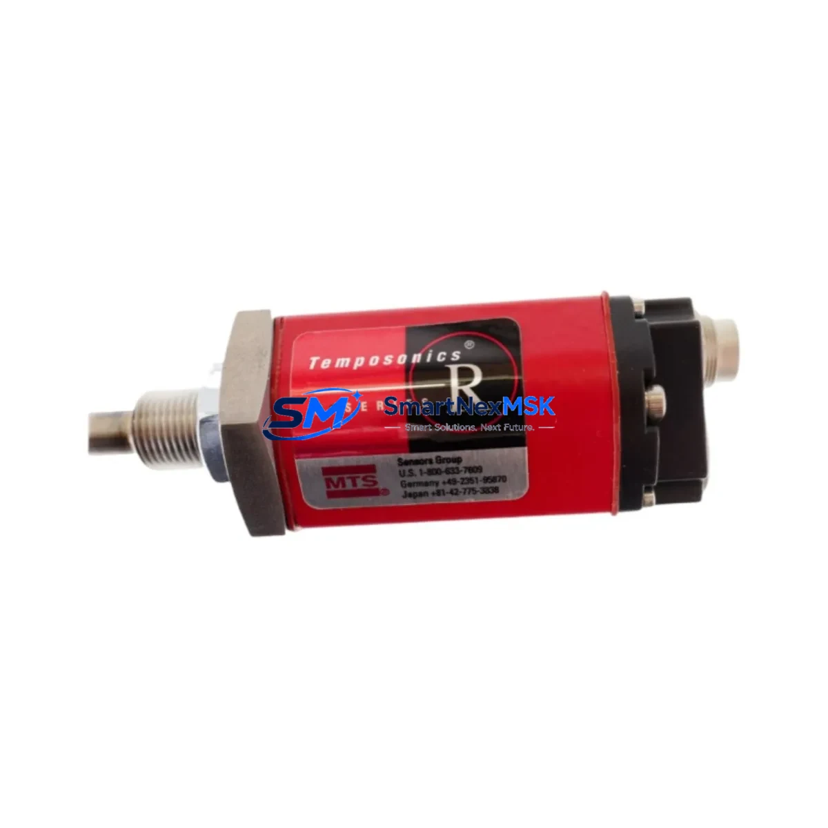
The MTS Temposonics RHM0165MD631P102 is a high-precision magnetostrictive linear position sensor from the R-Series product family, designed for demanding industrial automation and motion control applications. With a 165 mm stroke length and SSI (Synchronous Serial Interface) output, this unit is engineered as a direct retrofit replacement for aging or discontinued Temposonics sensors deployed across hydraulic press control systems, injection molding machines, metal forming lines, and precision assembly equipment.
When a legacy Temposonics sensor fails or reaches end-of-life, production lines face unplanned downtime and sourcing pressure. The RHM0165MD631P102 addresses this challenge directly: it maintains the same mechanical envelope, connector pinout, and SSI protocol framing as earlier R-Series variants, enabling engineers to execute a drop-in swap without modifying the control cabinet wiring, PLC program, or HMI screen layouts. This compatibility-first design philosophy is what makes it the preferred choice for retrofit planners and maintenance engineers managing aging automation infrastructure.
Before executing the replacement, engineers should verify several critical parameters. First, confirm the power supply capacity — the RHM0165MD631P102 operates on 24 VDC (±15%) and draws approximately 100 mA; ensure the existing 24V rail in the control cabinet can sustain this load alongside other field devices such as the Temposonics RHM0300MD631P102 or RHM0500MD631P102 sensors that may share the same power bus. Second, inspect the terminal wiring at the sensor connector: the SSI clock and data lines (CLK+, CLK−, DATA+, DATA−) must be correctly matched to the PLC’s SSI input module — commonly a Siemens SM 338 or equivalent SSI counter card — to avoid bit-shift errors in position feedback.
Backplane and rack compatibility should also be confirmed. In systems where the SSI input card is housed in a Siemens S7-300 rack or a Beckhoff EtherCAT terminal block, the module address assignment must be preserved from the original configuration. If the legacy sensor was addressed as a specific I/O node in the PLC project, the replacement unit must be commissioned to the same logical address to prevent program faults. Engineers using STEP 7 or TIA Portal should back up the existing hardware configuration before any physical swap.
Program compatibility is another key consideration. The RHM0165MD631P102 outputs a 25-bit or 26-bit SSI data word depending on the firmware variant; verify that the PLC’s SSI read function block is configured for the correct bit length and clock frequency (typically 100 kHz to 1 MHz). If the original sensor used a different bit-count configuration, a minor parameter adjustment in the function block — not a full program rewrite — is all that is required. HMI screens displaying position values should be validated post-swap to confirm scaling factors remain accurate.
Communication link integrity is equally important. In systems where the SSI signal travels over long cable runs (>10 m), use shielded twisted-pair cable and verify that the cable shield is grounded at one end only to prevent ground loops. If the existing installation uses a Temposonics RHM0165MD631P102 with a specific cable assembly (e.g., a 5-pin M12 connector), confirm the replacement unit ships with the same connector type or plan for a field-wirable connector adaptation.
Upgrade Compatibility Table
| Parameter | RHM0165MD631P102 (This Unit) | Retrofit Notes |
|---|---|---|
| Stroke Length | 165 mm | Must match legacy sensor stroke exactly |
| Output Interface | SSI (Synchronous Serial Interface) | Compatible with Siemens SM 338, Beckhoff EL5001, and equivalent SSI input modules |
| Supply Voltage | 24 VDC ±15% | Verify existing 24V rail capacity in control cabinet |
| Connector Type | M12 5-pin or flying leads (per order code) | Confirm connector variant matches existing cable assembly |
| Mounting Style | Rod-style (RHM profile) | Direct drop-in for existing RHM-profile mounting brackets |
| SSI Data Word | 25-bit / 26-bit (firmware dependent) | Verify PLC SSI function block bit-length setting |
| Communication Compatibility | SSI; optional PROFIBUS/EtherCAT variants available | Confirm protocol with PLC SSI input card specification |
| Installation Requirement | Standard R-Series rod mounting, position magnet required | Reuse existing position magnet if undamaged |
| Replacement Recommendation | Direct replacement for RHM0165MD631P102 and compatible R-Series variants | No mechanical modification required |
| Commissioning Focus | SSI clock frequency, bit-length, zero-point calibration | Validate position feedback in PLC and HMI after installation |
| Warranty | 12 Months | Covers manufacturing defects; includes pre-shipment functional test |
Retrofit Planning for Existing Automation Systems
A successful retrofit of the RHM0165MD631P102 into an existing automation system requires a structured approach that accounts for every component in the signal chain. Begin with a full audit of the control cabinet: identify the PLC CPU (such as a Siemens S7-315 or S7-317), the SSI input module, the 24V power supply module, and the terminal block wiring associated with the legacy sensor. Document the existing wiring diagram before disconnecting any terminals.
In systems where the position sensor feeds a closed-loop hydraulic axis, the SSI input card’s position data is typically consumed by a PID function block in the PLC. Before the swap, note the current zero-point offset and scaling parameters stored in the PLC data blocks — these values will need to be re-entered or verified after the new sensor is installed and powered. If the system uses a Rexroth HNC100 or similar hydraulic axis controller, the sensor interface parameters must also be rechecked in the axis controller’s configuration tool.
For systems that include a Siemens TP700 or TP1200 HMI panel displaying real-time position values, plan a brief HMI validation step after commissioning. The position display tag should reflect the correct engineering unit (mm) and range (0–165 mm) once the new sensor is live. If the HMI uses a trend display, clear historical data buffers to avoid displaying pre-swap position artifacts.
In multi-axis systems — for example, a hydraulic press with four independent cylinders each fitted with a Temposonics sensor — it is advisable to replace sensors one axis at a time, validating each axis before proceeding to the next. This approach limits exposure and allows the maintenance team to isolate any commissioning issues to a single axis without affecting overall machine availability. Keep spare components such as a Temposonics position magnet, M12 connector, and shielded sensor cable on hand to avoid secondary delays.
If the retrofit involves a protocol migration — for instance, moving from SSI to EtherCAT using a Temposonics RHM0165MD631V02 EtherCAT variant — additional steps are required: update the PLC’s I/O configuration, import the ESI (EtherCAT Slave Information) file for the new sensor, and remap all position data tags in the PLC program and HMI. In such cases, a Beckhoff EK1100 EtherCAT coupler or equivalent gateway may be needed to integrate the new sensor into the existing network topology.
Downtime Control During System Migration
Minimizing downtime during a sensor replacement is a primary concern for production engineers. The RHM0165MD631P102’s drop-in mechanical compatibility is the single most effective downtime-reduction factor: because no drilling, re-machining, or bracket fabrication is required, the physical swap can typically be completed in under 30 minutes by a trained technician.
To further compress downtime, prepare all materials before the maintenance window opens. This includes the replacement sensor (pre-tested and confirmed functional), the correct M12 cable assembly or flying-lead termination, a wiring diagram printout, and a laptop with TIA Portal or STEP 7 loaded with the current PLC project. If the system uses a Siemens S7-300 with a hardware configuration that requires re-downloading after an I/O change, pre-stage the project file and confirm the PLC is in STOP mode before beginning.
Protect the original program logic by creating a full PLC project backup before any intervention. Store the backup on a USB drive and a network share. If the SSI input module requires re-parameterization (clock frequency, bit count, gray code vs. binary), document the existing parameters from the module’s online diagnostics before powering down. This ensures that if the commissioning of the new sensor reveals an unexpected parameter mismatch, the original configuration can be restored within minutes.
After the physical installation, power up the system in a controlled sequence: energize the 24V sensor supply first, confirm the SSI signal is present on the input module’s diagnostic LEDs, then release the PLC from STOP to RUN. Monitor the position feedback value in the PLC’s watch table for 2–3 minutes to confirm stable, noise-free readings before resuming production. Document the commissioning date, sensor serial number, and zero-point calibration value in the machine’s maintenance log for future reference.
Retrofit Support FAQ
Q1: Is the RHM0165MD631P102 a direct replacement for my existing Temposonics R-Series sensor?
Yes, provided your existing sensor shares the same stroke length (165 mm), output interface (SSI), and rod-style (RHM) profile. The RHM0165MD631P102 is mechanically and electrically compatible with other R-Series SSI variants of the same stroke. Verify the order code suffix to confirm the connector type and SSI data format match your installation.
Q2: What commissioning steps are required after installation?
After physical installation, verify the SSI clock frequency and bit-length settings in your PLC’s SSI input module match the sensor’s output configuration. Perform a zero-point calibration if the sensor’s reference position differs from the legacy unit. Validate the position feedback value in the PLC watch table and confirm HMI displays reflect the correct engineering unit and range before returning the machine to production.
Q3: Can I reuse the existing wiring and connector from the old sensor?
In most cases, yes. If the existing cable assembly uses a standard M12 5-pin connector and the wiring follows the Temposonics R-Series pinout (CLK+, CLK−, DATA+, DATA−, GND, +24V), it can be reused directly. Inspect the cable for insulation damage, connector corrosion, or broken shield continuity before reuse. Replace the cable if any defects are found to avoid intermittent SSI signal errors.
Q4: What does the 12-month warranty cover, and is pre-shipment testing performed?
Every RHM0165MD631P102 unit supplied by SMARTNEXMSK undergoes a pre-shipment functional test to verify SSI output integrity, stroke linearity, and supply current draw. The 12-month warranty covers manufacturing defects in materials and workmanship from the date of shipment. It does not cover damage resulting from incorrect installation, overvoltage, or mechanical impact. Warranty claims are processed via sales@smartnexmsk.com with proof of purchase and a fault description.
© 2026 SMARTNEXMSK. All rights reserved.
Original Source: https://smartnexmsk.com
Contact: sales@smartnexmsk.com | +86 18259474341