MTU 0015381350 Maintenance-Ready Spare ADEC ECU: Spare Replacement & Industrial Downtime Risk Control
The MTU 0015381350 is the original ADEC (Advanced Diesel Engine Control) ECU motherboard designed for MTU Series 2000 and Series 4000 diesel engine platforms. As the central processing unit governing fuel injection timing, load management, fault diagnostics, and CAN-bus communication across the engine control architecture, this module is a mission-critical component in power generation, marine propulsion, rail traction, and heavy industrial drive systems. When this unit fails or degrades, the entire engine management system is compromised — making rapid, verified spare replacement the only path to restoring continuous operation.
At SMARTNEXMSK, every MTU 0015381350 unit is sourced from authorized supply channels, subjected to pre-shipment functional verification, and dispatched with a 12-month warranty. Our inventory is maintained specifically to support maintenance engineers and procurement teams who cannot afford extended lead times on critical engine control spares.
Spare Maintenance Table
| Parameter | Specification / Detail |
|---|---|
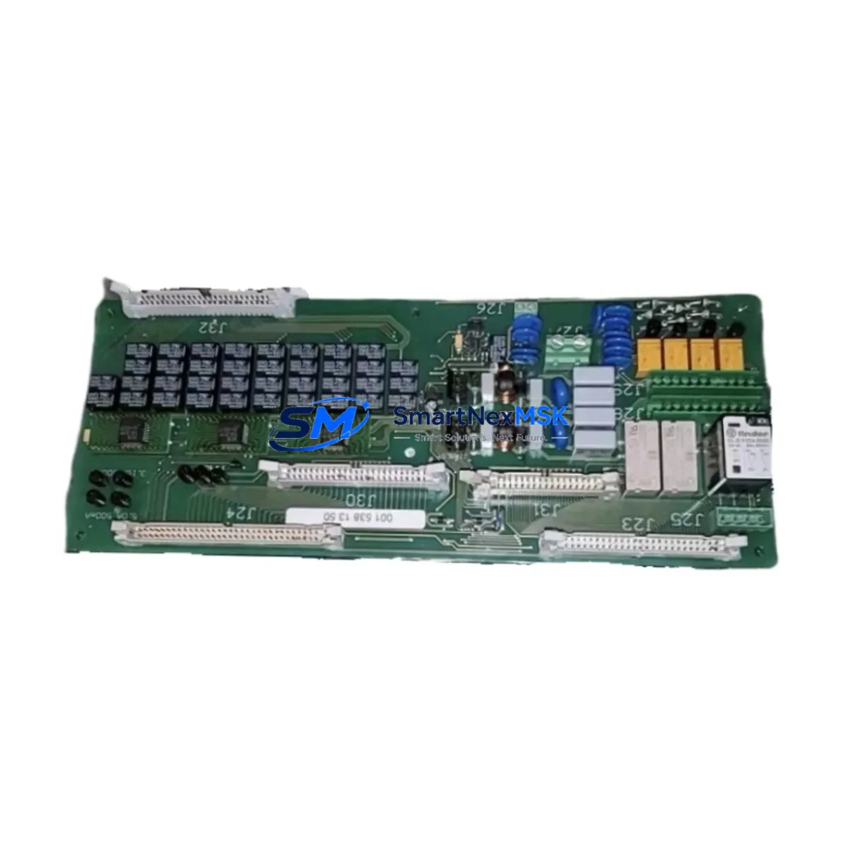
| Part Number | MTU 0015381350 |
| Description | ADEC ECU Motherboard (Engine Control Unit) |
| Compatible Series | MTU Series 2000, MTU Series 4000 |
| Brand / OEM | MTU (Rolls-Royce Power Systems) |
| Country of Origin | Germany (DE) |
| Communication Interface | CAN-bus (SAE J1939 protocol) |
| Operating Voltage | 24 VDC nominal (engine electrical system) |
| Application Environment | Power generation, marine, rail, industrial drive |
| Installation Type | Direct ECU housing replacement, OEM connector-compatible |
| Pre-Shipment Testing | Functional verification performed on every unit |
| Condition | Original spare (new or refurbished-to-spec, clearly stated per order) |
| Warranty | 12 months from date of shipment |
| Lead Time | In-stock: ships within 1–3 business days |
| Maintenance Recommendation | Replace at first sign of fault codes E1xxx/E2xxx or CAN-bus dropout; inspect every 8,000 operating hours |
Maintenance Planning for Continuous Operation
Replacing the MTU 0015381350 ADEC ECU is rarely an isolated task. Experienced maintenance engineers know that an ECU failure is often symptomatic of broader electrical stress across the engine control cabinet. A disciplined replacement workflow should include inspection of the following interconnected components to prevent repeat failures and ensure the engine returns to full operational specification.
Begin with the ADEC power supply module — the 24 VDC regulated supply feeding the ECU is a common failure point, and a degraded supply can damage a new ECU within weeks of installation. Verify output voltage stability under load before commissioning the replacement board. Next, inspect the CAN-bus wiring harness and termination resistors; corroded connectors or missing 120-ohm terminations will generate persistent communication faults that mimic ECU hardware failure.
The MTU ADEC I/O expansion modules connected to the ECU backbone should be checked for firmware version compatibility — mismatched firmware between the ECU and I/O nodes is a known source of intermittent faults on Series 4000 installations. Similarly, the engine speed sensors (magnetic pickup units) and their signal conditioning circuits should be tested; a noisy or weak speed signal can cause the ECU to log false overspeed or misfire events.
For installations with remote monitoring, the MTU ADEC gateway or DiaSys diagnostic interface module should be re-initialized after ECU replacement to clear historical fault logs and re-establish the communication session. Failure to do so often results in phantom alarms that confuse operators during the post-maintenance run-up.
In the engine control cabinet, inspect the 24 VDC battery-backed power distribution board, blade fuses and fuse holders on the ECU supply rail, and the main grounding bus. Poor ground continuity is a leading cause of ECU logic errors and CAN-bus instability. If the installation includes a PLC-based supervisory controller interfacing with the ADEC via Modbus or CAN, verify that the PLC I/O module and communication card are functioning correctly before returning the engine to service.
Finally, for long-running Series 2000 or Series 4000 installations approaching end-of-life, consider stocking a spare ADEC operator panel (local control unit) and a set of engine harness connector repair kits. These low-cost items prevent extended downtime when the primary ECU replacement reveals secondary wiring degradation — a situation that is far more common in engines with more than 40,000 operating hours.
Site Replacement Workflow
Step 1 — Pre-replacement documentation: Record all active fault codes using the MTU DiaSys or ADEC operator panel before powering down. Photograph the existing ECU connector orientation and wiring labels. Note the current engine operating hours and last service date.
Step 2 — Safe isolation: Shut down the engine and isolate the 24 VDC supply at the main distribution board. Wait a minimum of 5 minutes for capacitors to discharge before disconnecting the ECU harness connectors. Label each connector if not already marked.
Step 3 — Physical replacement: Remove the MTU 0015381350 from its housing. Install the replacement unit, ensuring all connectors are fully seated and locking clips are engaged. Verify that the ECU housing mounting screws are torqued to specification to maintain vibration resistance.
Step 4 — Parameterization and commissioning: Restore engine-specific parameters using DiaSys or the ADEC configuration tool. For Series 4000 engines, confirm that the injector trim codes and cylinder-specific calibration data are correctly loaded. Perform a no-load run-up and monitor CAN-bus traffic for error frames before applying load.
Step 5 — Post-replacement verification: Clear all fault codes after successful commissioning. Log the replacement in the maintenance record with the new unit’s serial number and the 12-month warranty start date. Schedule the next ECU inspection at 8,000 operating hours or 24 months, whichever comes first.
This workflow minimizes downtime, ensures system compatibility, and provides a documented audit trail for compliance and warranty purposes.
Spare Parts Support FAQ
Q1: Is the MTU 0015381350 compatible with both Series 2000 and Series 4000 engines?
Yes. The 0015381350 ADEC ECU motherboard is designed for use across the MTU Series 2000 and Series 4000 engine families. However, engine-specific parameterization is required during commissioning — the hardware is compatible, but the software configuration must match your engine variant. Always confirm your engine model and ADEC software version with our technical team before ordering if you are unsure.
Q2: How is each unit tested before shipment?
Every MTU 0015381350 unit dispatched by SMARTNEXMSK undergoes pre-shipment functional verification covering power-on self-test, CAN-bus communication integrity, and I/O channel continuity. Units that do not pass verification are not shipped. A test report is available upon request for critical installations.
Q3: What does the 12-month warranty cover, and how is a warranty claim handled?
The 12-month warranty covers manufacturing defects and functional failures under normal operating conditions. It does not cover damage caused by incorrect installation, overvoltage events, or physical impact. To initiate a warranty claim, contact sales@smartnexmsk.com with your order number, fault description, and DiaSys fault log if available. Replacement or repair is processed within 5 business days of receiving the returned unit.
Q4: Can SMARTNEXMSK support long-term spare parts supply for aging MTU ADEC systems?
Yes. We maintain standing inventory of MTU ADEC components specifically to support facilities operating legacy Series 2000 and Series 4000 installations beyond the OEM active support window. We recommend that maintenance planners establish a minimum stock of one spare ECU per engine cluster for critical applications. Contact us to discuss a long-term supply agreement with reserved stock allocation and priority dispatch terms.
© 2026 SMARTNEXMSK. All rights reserved.
Original Source: https://smartnexmsk.com
Contact: sales@smartnexmsk.com | +86 18259474341