Nano-Box N4BST022 Retrofit-Ready PLC Board for N4B Series Control Systems
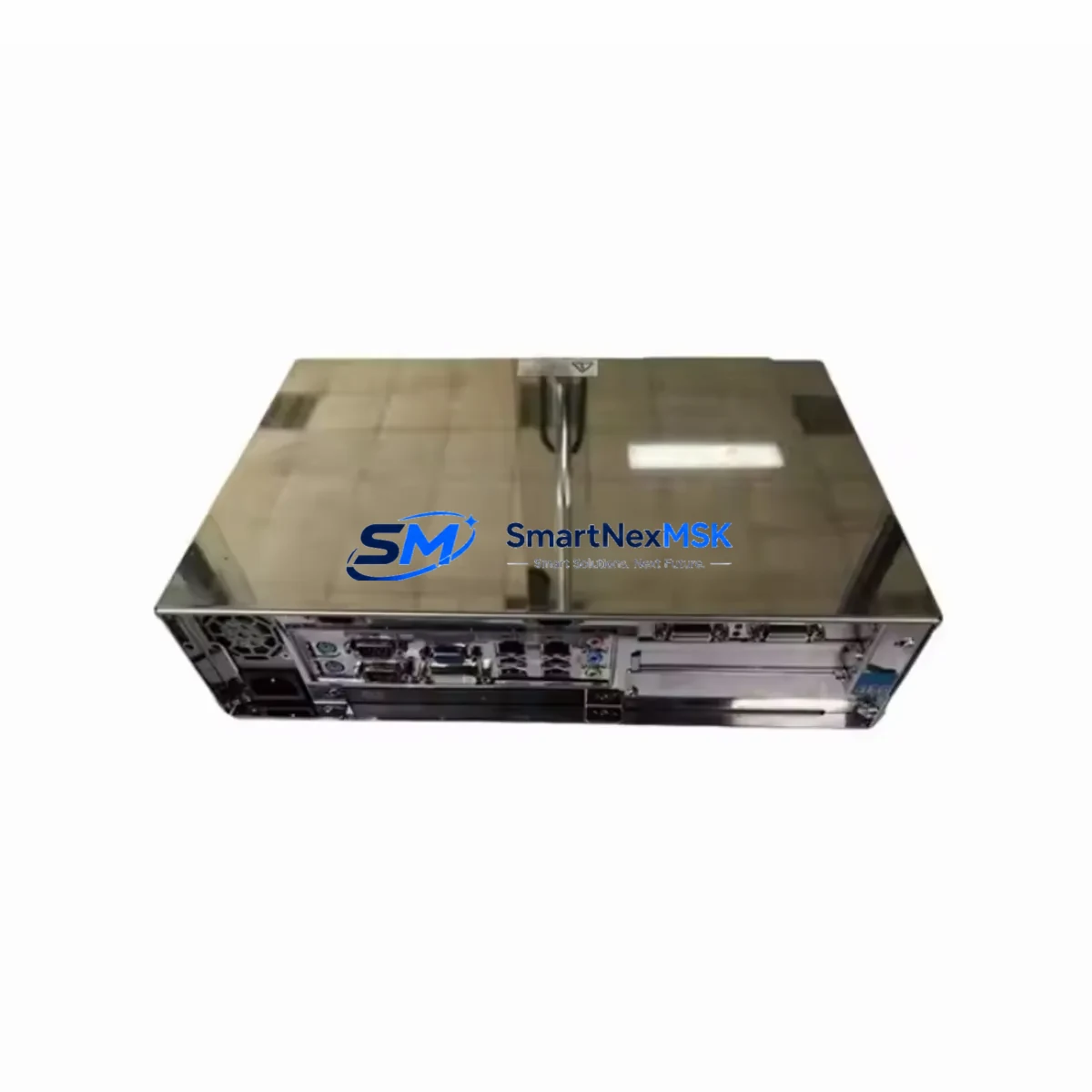
The Nano-Box N4BST022 is a retrofit-ready PLC control board engineered for seamless integration into existing N4B Series control systems. Whether you are replacing a discontinued module, upgrading an aging control cabinet, or restoring a production line after an unexpected failure, the N4BST022 delivers verified hardware compatibility, stable communication performance, and a straightforward commissioning path that minimizes engineering risk and unplanned downtime.
Industrial facilities running legacy Nano-Box N4B platforms frequently encounter end-of-life supply constraints on original control boards. The N4BST022 is stocked specifically to address this gap — providing a direct hardware replacement that preserves existing terminal wiring layouts, backplane connector pinouts, and rack mounting dimensions. Engineers can install the N4BST022 without redesigning the control cabinet or modifying the existing DIN rail assembly, making it the preferred choice for maintenance teams operating under tight shutdown windows.
Upgrade Compatibility Table
| Parameter | Detail |
|---|---|
| SKU | N4BST022 |
| Brand | Nano-Box |
| Compatible Series | N4B Series PLC Control Systems |
| Form Factor | Direct drop-in replacement; matches original rack slot dimensions |
| Backplane Interface | Compatible with standard N4B backplane bus connector |
| Terminal Wiring | Retains original terminal block layout; no rewiring required in most installations |
| Communication Compatibility | Supports RS-232, RS-485 serial protocols standard to N4B platform |
| Power Supply Requirement | 24 VDC nominal; verify existing N4B power module (e.g. N4B-PSU series) output capacity before installation |
| Module Address Configuration | DIP switch or software-configurable; confirm address map against existing rack layout |
| Program Compatibility | Retains existing ladder logic and function block programs; full re-download recommended after swap |
| HMI Screen Compatibility | Compatible with existing N4B-linked HMI panels; verify tag address mapping post-installation |
| Installation Requirement | Power-off installation; ESD precautions required |
| Commissioning | Re-download program, verify I/O scan, confirm communication link, test HMI screens |
| Warranty | 12 Months from date of shipment |
| Origin | China (CN) |
| Stock Status | Available — ships from existing inventory |
Retrofit Planning for Existing Automation Systems
A successful N4BST022 retrofit begins well before the module arrives on site. Maintenance engineers should start by auditing the existing control cabinet to confirm the N4B Series rack slot assignment, the current backplane bus revision, and the power budget available from the installed N4B power supply module. In multi-rack configurations, the rack address and I/O module mapping must be documented before the old board is removed to avoid address conflicts during recommissioning.
Terminal wiring on the N4BST022 follows the standard N4B terminal block convention, which means field wiring for digital inputs, digital outputs, and analog channels can typically be transferred directly from the legacy board without modification. However, engineers should photograph and label all terminal connections before disconnection — particularly on installations where the original wiring documentation is incomplete or outdated.
Communication links are a critical checkpoint in any N4B retrofit. If the existing system uses an N4B RS-485 communication module or a dedicated Modbus RTU gateway to connect field devices, SCADA systems, or remote I/O stations, the baud rate, parity, stop bits, and station address settings must be recorded and re-applied after the N4BST022 is installed. In systems where a Nano-Box N4B Ethernet communication card handles upstream connectivity to a DCS or MES layer, the IP address configuration and network timeout parameters should be verified against the plant network documentation.
For facilities upgrading from older N4B control boards to the N4BST022, the I/O expansion architecture deserves careful attention. Existing N4B digital input modules, N4B digital output modules, and N4B analog I/O modules installed in the same rack will continue to operate normally, provided the backplane bus is intact and the module scan order in the control program is preserved. If the retrofit is part of a broader system expansion — for example, adding new I/O points or integrating a Nano-Box N4B thermocouple input module — the program must be updated to include the new module addresses before the system is returned to service.
HMI integration is another area that requires pre-commissioning verification. Existing Nano-Box N4B-compatible HMI panels communicate with the control board via serial or Ethernet links. After installing the N4BST022, engineers should confirm that the HMI communication driver settings match the new board’s port configuration, and that all screen tags resolve correctly against the updated program data block. A full HMI screen walkthrough under simulated process conditions is recommended before returning the system to automatic operation.
Programming cable compatibility should also be confirmed before the retrofit window begins. The standard Nano-Box N4B programming cable (USB-to-serial or RS-232 type, depending on the engineering workstation) is required to download the verified program to the N4BST022. Ensure the programming software version on the engineering laptop is compatible with the N4BST022 firmware revision to avoid download errors during the commissioning phase.
Downtime Control During System Migration
Minimizing production downtime during a PLC control board replacement requires a structured pre-shutdown preparation process. Before the maintenance window begins, the engineering team should export and archive the current program from the existing N4B control board using the Nano-Box programming software. This backup serves as the recovery baseline if any issue arises during the swap. The program file, including all data registers, retentive memory values, and communication parameters, should be stored on both the engineering laptop and a secure network location.
During the physical swap, the N4BST022 should be installed in the same rack slot as the original board, with all terminal connections transferred in sequence according to the pre-documented wiring layout. Power should remain off throughout the installation. Once the module is seated and secured, power can be restored and the program downloaded to the N4BST022 via the programming cable. The I/O scan should be verified in online monitoring mode before switching the system from manual to automatic control.
To further reduce risk, facilities with redundant control paths or bypass circuits should activate these during the swap window to maintain partial process continuity. For critical production lines where even brief interruptions are costly, a pre-tested spare N4BST022 unit — pre-loaded with the verified program — can be prepared in advance, reducing the active swap time to under 30 minutes in most N4B rack configurations. All commissioning steps, including communication link verification, HMI screen confirmation, and I/O functional test, should be completed and signed off before the maintenance window is closed.
Retrofit Support FAQ
Q1: Is the N4BST022 a direct replacement for the original N4B Series control board?
Yes. The N4BST022 is designed as a direct hardware replacement for compatible N4B Series control boards. It matches the original rack slot dimensions, backplane connector pinout, and terminal block layout. In most installations, field wiring can be transferred without modification. A full program re-download and I/O verification are required after installation.
Q2: What commissioning steps are required after installing the N4BST022?
After physical installation, download the verified program to the N4BST022 via the Nano-Box programming cable. Verify the I/O scan in online monitoring mode, confirm all communication links (serial, Ethernet, or Modbus as applicable), and perform a full HMI screen walkthrough to confirm tag resolution. Document all commissioning steps and obtain sign-off before returning the system to automatic operation.
Q3: How do I verify wiring and communication compatibility before the maintenance window?
Review the existing N4B wiring diagrams and confirm terminal block assignments against the N4BST022 specification. Record all communication port settings (baud rate, parity, station address) from the existing board before removal. For Ethernet-connected systems, document the IP address and network parameters. Pre-stage the N4BST022 with the verified program and communication settings to minimize active installation time.
Q4: What does the 12-month warranty cover, and has the unit been tested before shipment?
Every N4BST022 unit undergoes functional testing prior to shipment, including power-on verification and communication port checks. The 12-month warranty covers manufacturing defects and hardware failures under normal operating conditions from the date of shipment. Units showing physical damage from improper installation or electrical overstress are not covered. Contact sales@smartnexmsk.com for warranty claims or technical support.
© 2026 SMARTNEXMSK. All rights reserved.
Original Source: https://smartnexmsk.com
Contact: sales@smartnexmsk.com | +86 18259474341