NIKKI NA50-40NAMKNN-CE Spare for NA50 Series Automation: Precision Spare Parts Replacement for Industrial Downtime Control
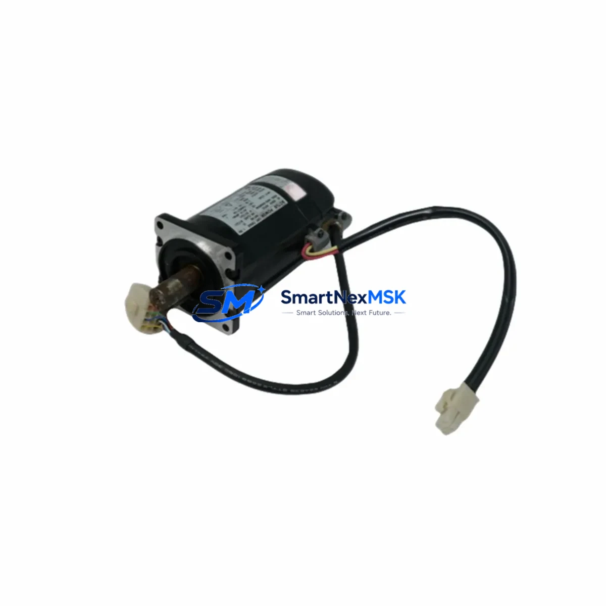
The NIKKI NA50-40NAMKNN-CE is an original AC servo motor engineered for the NA50 series automation platform by NIKKI DENSO. Designed for continuous-duty industrial environments, this unit delivers precise torque control, stable closed-loop feedback, and CE-certified electromagnetic compatibility — making it a critical maintenance spare for production lines, CNC machinery, packaging equipment, and automated assembly systems across manufacturing facilities.
When a servo motor fails on the production floor, every minute of unplanned downtime translates directly into lost output and escalating recovery costs. Stocking the NA50-40NAMKNN-CE as a verified maintenance spare eliminates the lead-time risk associated with OEM procurement channels and ensures your maintenance team can execute a same-shift replacement without waiting for factory delivery. Each unit shipped by SMARTNEXMSK undergoes pre-shipment electrical testing and is backed by a 12-month warranty, giving procurement engineers the confidence to commit to long-term spare parts inventory strategies.
Spare Maintenance Table
| Parameter | Specification |
|---|---|
| Part Number / SKU | NA50-40NAMKNN-CE |
| Brand / Manufacturer | NIKKI DENSO |
| Series | NA50 |
| Product Type | AC Servo Motor |
| Certification | CE (Electromagnetic Compatibility) |
| Origin | Japan |
| Rated Output | 400 W (inferred from NA50-40 designation) |
| Encoder Type | Incremental / Absolute (NA50 series standard) |
| Mounting Interface | Flange mount, compatible with NA50 series drive couplings |
| Operating Environment | Industrial automation, CNC, packaging, assembly lines |
| Compatibility | NIKKI DENSO NA50 series servo drives and controllers |
| Maintenance Role | Direct replacement spare; drop-in compatible with NA50 platform |
| Pre-Shipment Testing | Electrical continuity, insulation resistance, encoder signal verification |
| Warranty | 12 Months from date of shipment |
| Weight | 1,450 g (approx.) |
Maintenance Planning for Continuous Operation
Replacing the NA50-40NAMKNN-CE in the field is rarely an isolated task. Experienced maintenance engineers understand that a servo motor failure is often symptomatic of broader stress within the drive circuit or control cabinet. Before returning the system to production, a structured inspection of adjacent components is strongly recommended to prevent repeat failures and ensure long-term system stability.
Begin with the NIKKI DENSO NA50 series servo drive amplifier — the motor’s paired drive unit. Inspect for fault codes, capacitor bulging, and IGBT thermal stress. If the motor failed due to overcurrent or locked-rotor conditions, the drive’s internal protection circuits may have absorbed transient damage that is not immediately visible. Simultaneously, check the servo drive power supply module for output voltage stability; an unstable DC bus voltage is a common root cause of premature motor winding failure.
Inspect the encoder feedback cable and its shielded connector at both the motor and drive ends. Encoder signal degradation — often caused by cable flex fatigue, connector corrosion, or EMI ingress — can produce erratic positioning errors that are misdiagnosed as motor faults. Replace the cable if continuity or shield integrity is in question. Similarly, examine the motor power cable (U/V/W phase leads) for insulation cracking, terminal looseness, or signs of overheating at the connector body.
Within the control cabinet, verify the condition of the 24 VDC control power supply that feeds the servo enable signal and I/O interface. A marginal control supply can cause intermittent enable faults that stress the motor during repeated start-stop cycles. Check the I/O terminal block connections for the servo ready, alarm, and positioning complete signals — loose terminals in high-vibration environments are a frequent source of nuisance faults. If the system uses a safety relay module for STO (Safe Torque Off) or emergency stop integration, confirm that the relay contacts are within specification and that the response time meets the machine’s safety function requirements.
For systems with communication modules — whether PROFIBUS-DP, EtherCAT, or MECHATROLINK — verify that the network topology remains intact after the motor swap and that the drive’s node address and baud rate settings are correctly restored. If the machine uses a PLC or motion controller to coordinate multi-axis positioning, re-run the axis homing sequence and confirm that position offsets are within tolerance before resuming production. Where applicable, inspect the regenerative braking resistor for signs of thermal discoloration, which may indicate that the drive has been operating at the edge of its deceleration capacity.
Finally, review the fuse and circuit breaker ratings on the motor’s power feed circuit. An undersized or aging fuse that has experienced repeated thermal cycling may have a degraded interrupting capacity, posing a risk during the next overcurrent event. Replacing fuses as a matter of course during a servo motor changeout is a low-cost step that significantly reduces the risk of a secondary failure.
Site Replacement Workflow
Step 1 — Isolation and Lockout: De-energize the servo drive and apply LOTO (Lockout/Tagout) to the main power disconnect. Allow the DC bus capacitors to discharge fully — typically 5 minutes minimum — before opening the drive enclosure or disconnecting motor cables.
Step 2 — Documentation: Photograph the existing motor nameplate, cable routing, and connector orientation before disassembly. Record the drive’s current parameter set (servo gain, encoder resolution, electronic gear ratio) either via the drive’s parameter backup function or manually. This data is essential for commissioning the replacement unit.
Step 3 — Mechanical Removal: Disconnect the motor power cable and encoder cable. Remove the motor mounting bolts and carefully extract the motor from the coupling or gearbox interface. Inspect the coupling for wear, misalignment, or fretting corrosion before installing the replacement.
Step 4 — Installation of NA50-40NAMKNN-CE: Mount the replacement motor, ensuring correct coupling alignment within the manufacturer’s specified tolerance. Reconnect the motor power cable (observe U/V/W phase sequence) and encoder cable. Verify that all connector locks are fully engaged and that cable shielding is properly grounded at the drive end.
Step 5 — Parameter Restore and Test: Restore the drive parameter set from backup. Power up the system and clear any residual fault codes. Perform a low-speed jog test to confirm encoder feedback direction and motor rotation direction. Execute the axis homing sequence and verify positioning accuracy before returning the machine to automatic mode.
Step 6 — Run-In and Handover: Operate the axis through several production cycles at reduced speed, monitoring motor temperature, drive current, and position error. Document the replacement in the maintenance log and update the spare parts inventory record.
Spare Parts Support FAQ
Q1: Is the NA50-40NAMKNN-CE a direct drop-in replacement for the original NIKKI DENSO unit?
Yes. The NA50-40NAMKNN-CE is an original NIKKI DENSO component manufactured to the same mechanical and electrical specification as the series-production unit. No parameter changes to the servo drive are required beyond restoring the existing parameter backup, provided the drive firmware version is compatible with the NA50 series motor interface.
Q2: What pre-shipment testing is performed before dispatch?
Each unit undergoes electrical continuity testing across all motor phase windings, insulation resistance measurement between windings and frame ground, and encoder signal output verification. Units that do not meet specification thresholds are quarantined and not shipped. A test record is available upon request for quality-critical applications.
Q3: How should the NA50-40NAMKNN-CE be stored as a long-term maintenance spare?
Store the unit in its original packaging in a dry, temperature-controlled environment (recommended: 5–40°C, relative humidity below 75% non-condensing). Avoid storage near strong magnetic fields or corrosive atmospheres. Rotate the motor shaft manually every six months to prevent bearing brinelling during extended storage. The unit’s 12-month warranty period begins from the date of shipment, not the date of installation.
Q4: Can SMARTNEXMSK support long-term or blanket-order supply of the NA50-40NAMKNN-CE?
Yes. SMARTNEXMSK supports scheduled delivery agreements and blanket purchase orders for maintenance-critical spare parts. This is particularly valuable for facilities operating multiple NA50-series axes, where a single stock position can cover several machines. Contact our sales team to discuss volume pricing, lead-time commitments, and consignment stock arrangements tailored to your maintenance planning cycle.
© 2026 SMARTNEXMSK. All rights reserved.
Original Source: https://smartnexmsk.com
Contact: sales@smartnexmsk.com | +86 18259474341