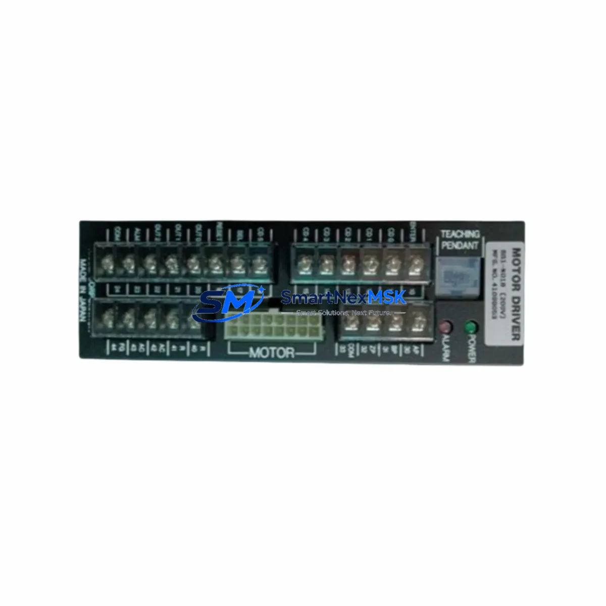
NISSEI BS1-N018 Retrofit-Ready Servo Gearhead for BS1 Series Control Systems
The NISSEI BS1-N018 is a precision inline servo gearhead engineered for seamless integration into BS1 Series servo drive systems. As legacy automation lines age and OEM support for discontinued models becomes increasingly limited, the BS1-N018 stands out as a reliable, drop-in retrofit solution that preserves mechanical mounting geometry, shaft coupling dimensions, and output torque characteristics — enabling engineers to restore or upgrade motion control performance without redesigning the surrounding mechanical structure.
Whether you are replacing a worn-out unit on a packaging line, upgrading a legacy CNC axis, or restoring a precision assembly station, the BS1-N018 delivers the dimensional and performance compatibility that retrofit projects demand. Its compact inline design integrates directly with standard NISSEI BS1 Series servo motors, and its output flange and shaft specifications match the original installation envelope, minimizing downtime during changeover.
For retrofit planning, engineers should verify the following before installation: input shaft bore and keyway dimensions, output shaft diameter and length, gear ratio (N018 denotes a specific reduction ratio within the BS1 family), mounting flange bolt pattern, and backlash specification. These parameters must align with the existing servo motor — typically a NISSEI or compatible third-party AC servo motor — and the driven load coupling. If the original gearhead was paired with a NISSEI servo amplifier or drive controller, the reflected inertia and torque ripple characteristics of the BS1-N018 should be confirmed against the drive’s tuning parameters to avoid resonance or instability after replacement.
In systems where the BS1-N018 interfaces with a motion controller — such as a multi-axis servo controller, a PLC-based positioning module, or a dedicated CNC interpolator — no software changes are typically required, as the gearhead is a purely mechanical component. However, if the gear ratio differs from the original unit, axis scaling parameters in the controller or HMI must be updated to reflect the new pulses-per-unit or encoder counts-per-revolution relationship. This is a common adjustment step in retrofit projects involving NISSEI BS1 Series gearheads across different ratio variants.
The BS1-N018 is also frequently deployed alongside complementary components in control cabinet and field retrofit scenarios. In a typical servo axis upgrade, the gearhead works in conjunction with a servo motor, a servo amplifier or drive unit, a regenerative resistor or braking module, and a feedback cable assembly. For multi-axis systems, a servo bus coupler or axis expansion module may be present in the control cabinet. Engineers replacing the BS1-N018 should also inspect the flexible coupling or bellows coupling connecting the gearhead output to the load, as these wear components are often replaced simultaneously to restore full system accuracy. In applications where the original installation used a torque limiter or overload clutch between the gearhead and the driven mechanism, these should be inspected and recalibrated after the gearhead swap.
For systems migrating from older NISSEI BS1 Series configurations to newer servo platforms, the BS1-N018 can serve as an interim mechanical solution while the electrical drive system is upgraded in stages. This phased approach — replacing the gearhead first, then upgrading the servo amplifier and motor in a subsequent maintenance window — is a proven strategy for minimizing production disruption on continuous manufacturing lines. It allows the mechanical retrofit to be validated independently before the electrical changeover, reducing the risk of compounded faults during commissioning.
Upgrade Compatibility Table
| Parameter | Details |
|---|---|
| Model | NISSEI BS1-N018 |
| Series | BS1 Series |
| Type | Inline Servo Gearhead |
| Origin | Japan |
| Mounting Interface | BS1 Series servo motor flange (direct-mount compatible) |
| Output Shaft | Solid shaft, standard BS1 Series dimensions |
| Gear Ratio | N018 designation (confirm exact ratio from nameplate) |
| Backlash | Low-backlash precision grade, suitable for positioning applications |
| Lubrication | Grease-packed, maintenance-free under normal operating conditions |
| Replacement Compatibility | Direct retrofit for original NISSEI BS1-N018 installations |
| Communication / Protocol | N/A (mechanical component; no electrical interface) |
| Commissioning Notes | Verify gear ratio, update axis scaling in controller/HMI if ratio changed |
| Weight | 1,230 g (approx.) |
| Warranty | 12-Month Warranty — tested before shipment, full replacement support |
Retrofit Planning for Existing Automation Systems
A successful BS1-N018 retrofit begins with a thorough audit of the existing servo axis. Start by documenting the current servo motor model — typically a NISSEI BS1 Series AC servo motor or an equivalent third-party unit — and confirm that the motor’s output shaft and flange dimensions match the BS1-N018 input interface. In many legacy installations, the servo motor is paired with a dedicated servo amplifier or drive unit mounted in the control cabinet. Before removing the gearhead, record the drive’s current tuning parameters, including gain settings, inertia ratio, and any electronic gear ratio settings, as these may need adjustment after the mechanical replacement.
In the control cabinet, the servo amplifier is typically connected to a PLC or motion controller via a fieldbus or pulse-direction interface. Common configurations include a servo drive receiving position commands from a positioning module or a multi-axis motion controller. If the system uses an encoder feedback cable routed from the servo motor back to the drive, inspect the cable and connector for wear during the gearhead replacement — this is an opportune moment to replace aging feedback cables that could cause intermittent faults after the retrofit is complete.
For systems that include a servo bus terminal block or I/O terminal module for safety interlocks and enable signals, verify that the servo-ready and alarm output signals are functioning correctly before and after the gearhead swap. In applications where a safety relay module or emergency stop circuit monitors the servo axis, the retrofit procedure should include a functional test of the safety chain to confirm that the new gearhead installation has not introduced any mechanical binding or overload conditions that could trigger a fault.
If the retrofit involves upgrading from an older BS1 Series gearhead variant to the BS1-N018, review the HMI screen associated with the axis for any displayed gear ratio or mechanical ratio parameters. Update these values in the HMI project and re-download the screen to the operator panel after commissioning. In systems using a programming cable or USB-to-serial adapter for drive parameter backup, ensure that the original parameter file is saved before any changes are made, providing a recovery baseline if the retrofit requires rollback.
Finally, for applications in packaging, assembly, or material handling where the servo axis drives a conveyor, rotary indexer, or pick-and-place mechanism, perform a low-speed jog test after installation to confirm smooth rotation and correct direction of travel before returning the system to automatic mode.
Downtime Control During System Migration
Minimizing downtime during a BS1-N018 gearhead replacement requires preparation, parallel staging, and a structured commissioning sequence. The most effective approach is to pre-stage the replacement unit — confirming all mechanical dimensions, gear ratio, and mounting hardware — before the scheduled maintenance window begins. This eliminates discovery delays during the actual changeover and keeps the mechanical swap to a minimum duration.
Before shutdown, back up all relevant controller parameters: servo drive gain settings, electronic gear ratio, homing offsets, and any axis-specific data stored in the PLC or motion controller. If the system uses a battery-backed memory module or a non-volatile parameter storage card in the drive, verify that the backup is current. This ensures that if any parameter is inadvertently altered during the retrofit, the system can be restored to its pre-retrofit state quickly.
During the mechanical swap, protect the servo motor shaft and encoder from contamination and mechanical shock. Use appropriate coupling alignment tools to ensure that the new gearhead is concentric with the motor shaft and the driven load. Misalignment at this stage is a leading cause of premature bearing wear and vibration after retrofit. Once the gearhead is installed and the coupling is secured, perform a manual rotation check before energizing the drive to confirm that there is no binding or unusual resistance in the drivetrain.
After energizing, perform a servo-on test at reduced speed before returning to full production speed. Monitor the drive’s current feedback and position error during the initial jog to confirm that the system is operating within expected parameters. If the gear ratio has changed, update the axis scaling in the controller and verify that the HMI position display matches the actual mechanical position before enabling automatic cycle operation. With proper preparation, a BS1-N018 retrofit can typically be completed within a single planned maintenance shift, keeping unplanned production loss to a minimum.
Retrofit Support FAQ
Q1: Is the BS1-N018 a direct drop-in replacement for the original NISSEI BS1-N018?
Yes. The BS1-N018 is manufactured to the original NISSEI BS1 Series dimensional and performance specifications. Mounting flange, input shaft bore, output shaft dimensions, and gear ratio are consistent with the original unit, making it a direct mechanical replacement in most installations. Always verify the nameplate gear ratio and shaft dimensions against your existing installation before ordering.
Q2: What commissioning steps are required after installing the BS1-N018?
For a same-ratio replacement, commissioning is typically limited to a mechanical alignment check, a low-speed jog test, and verification of position accuracy. If the gear ratio differs from the original unit, update the electronic gear ratio or axis scaling parameters in the servo drive and motion controller, and re-verify the HMI position display. A full servo tuning re-run is generally not required for a same-ratio swap.
Q3: Does the BS1-N018 come with a warranty and pre-shipment testing?
Yes. Every BS1-N018 unit supplied by SMARTNEXMSK is covered by a 12-month warranty from the date of shipment. Each unit undergoes functional testing before dispatch to verify mechanical rotation, backlash within specification, and absence of abnormal noise or resistance. Documentation is available upon request.
Q4: Can SMARTNEXMSK support long-term supply for ongoing maintenance requirements?
Yes. SMARTNEXMSK maintains stock of NISSEI BS1 Series gearheads and related servo components to support customers with ongoing maintenance, planned replacement programs, and emergency breakdown requirements. Contact our team to discuss volume pricing, lead times, and consignment stock arrangements for high-usage sites.
© 2026 SMARTNEXMSK. All rights reserved.
Original Source: https://smartnexmsk.com
Contact: sales@smartnexmsk.com | +86 18259474341