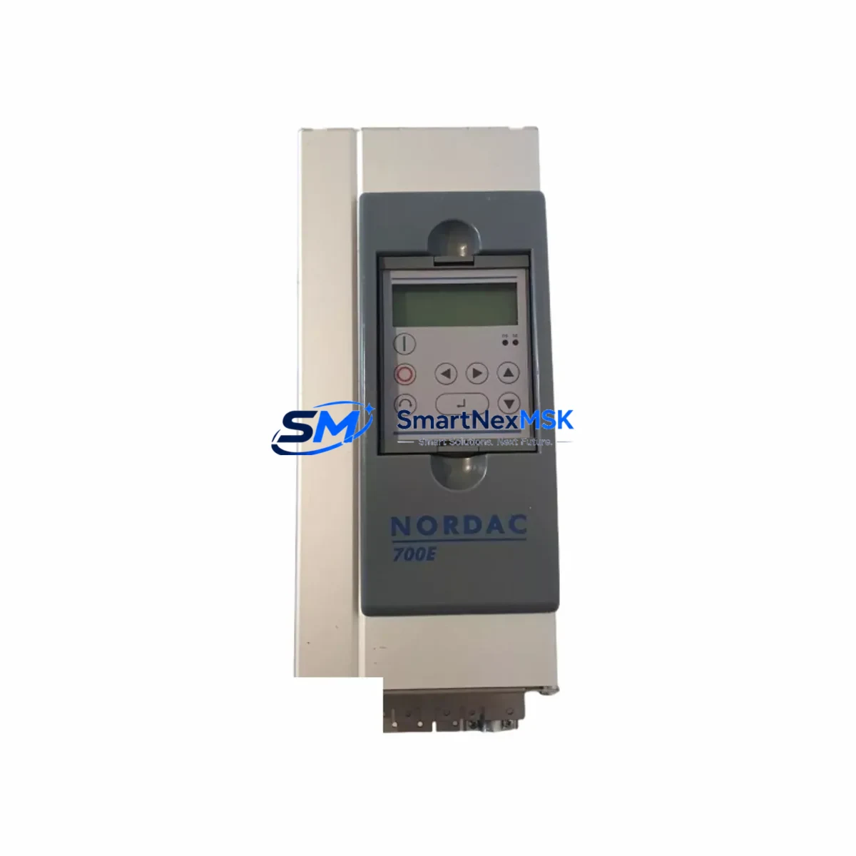
NORDAC SK700E-112-340-A-GBB-EL Retrofit-Ready VFD for SK700E Control Systems
The NORDAC SK700E-112-340-A-GBB-EL is an 11 kW (15 HP) three-phase variable frequency drive engineered by Nord Drivesystems for demanding industrial motor control applications. As legacy SK700E series drives reach end-of-life across manufacturing plants, packaging lines, conveyor systems, and pump stations, this unit serves as the authoritative retrofit and replacement solution — preserving existing wiring infrastructure, motor parameters, and control logic while delivering modern drive performance.
Whether you are replacing a failed unit on an emergency basis, executing a planned control cabinet upgrade, or migrating an aging automation system to a more maintainable platform, the SK700E-112-340-A-GBB-EL provides the dimensional compatibility, terminal layout, and parameter structure required for a smooth, low-downtime changeover.
Upgrade Compatibility Table
| Attribute | Detail |
|---|---|
| Model / Full SKU | SK700E-112-340-A-GBB-EL |
| Series | NORDAC SK700E |
| Rated Power | 11 kW (15 HP) |
| Input Voltage | 3-phase 380–480 V AC, 50/60 Hz |
| Output Current | ~25 A (nominal) |
| Enclosure / Protection | IP20 (panel-mount); GBB = built-in braking resistor interface |
| Communication Interface | EL suffix = integrated EtherNet/IP or EtherCAT fieldbus option |
| Mounting | DIN rail / backplate; compatible with SK700E series rack dimensions |
| Replacement Compatibility | Direct retrofit for SK700E-112-340-A and SK700E-112-340-A-GBB variants |
| Terminal Wiring | Identical terminal block layout to predecessor SK700E models; no rewiring required in most installations |
| Parameter Migration | Parameters uploadable via NORDAC ACCESS or SK TU4-CAO programming adapter |
| Debugging Focus | Motor data set, ramp times, fieldbus node address, braking resistor threshold |
| Warranty | 12 months from date of shipment |
Retrofit Planning for Existing Automation Systems
A successful SK700E-112-340-A-GBB-EL retrofit begins well before the drive arrives on site. Engineers should first audit the existing control cabinet to confirm available power supply capacity — the 11 kW drive requires a stable 380–480 V three-phase feed with adequate short-circuit protection, typically a 32 A motor circuit breaker or equivalent. If the original installation used a NORDAC SK700E-112-340-A without the GBB braking resistor interface, verify whether a dynamic braking resistor is connected and confirm the resistor’s resistance and wattage rating before energizing the replacement unit.
Terminal block compatibility is one of the most time-sensitive verification steps. The SK700E-112-340-A-GBB-EL retains the standard SK700E control terminal layout, meaning existing 24 V digital inputs, analog speed reference signals (0–10 V or 4–20 mA), relay outputs, and enable/fault wiring can typically be reconnected without modification. However, engineers should cross-reference the original wiring diagram against the replacement unit’s terminal assignment sheet, particularly for any site-specific parameter assignments on terminals X5 and X6.
For systems using a NORDAC SK TU4-CAO CANopen communication module or an SK TU4-PBR PROFIBUS-DP adapter, the fieldbus node address stored in the original drive must be documented before removal and re-entered during commissioning of the replacement. In EtherNet/IP or EtherCAT configurations — indicated by the EL suffix — the IP address or node ID assignment should be confirmed with the network administrator and re-applied via the NORDAC ACCESS software tool or the drive’s integrated keypad.
Backplane and rack integration is straightforward for installations where the SK700E-112-340-A-GBB-EL is mounted alongside other Nord Drivesystems components such as the SK 700E power supply module, SK TIE4 expansion I/O modules, or SK CSX-3A safety modules. The mechanical footprint and DIN rail spacing are consistent across the SK700E family, allowing the replacement drive to slot into the existing cabinet layout without structural modification.
Where the original system includes a NORDAC LINK decentralized drive bus or a higher-level controller such as a Siemens S7-300 or S7-1200 PLC communicating via PROFIBUS or PROFINET, the GSD or GSDML device description file for the SK700E-112-340-A-GBB-EL should be imported into the PLC engineering tool (STEP 7 or TIA Portal) to ensure correct I/O mapping. If the HMI panel — for example a Siemens TP700 or similar operator panel — displays drive status, speed, or fault codes via the fieldbus, the HMI screen tags should be verified against the new drive’s process data object (PDO) mapping before go-live.
For multi-axis systems where the SK700E-112-340-A-GBB-EL operates alongside additional SK700E or SK750E drives on a shared DC bus or common braking resistor bank, the braking energy distribution must be recalculated to confirm the replacement unit’s braking transistor threshold is correctly set. This is especially important in hoist, crane, or regenerative conveyor applications where braking duty cycles are high.
Downtime Control During System Migration
Minimizing production downtime during a drive replacement requires a structured pre-commissioning approach. Before shutting down the existing SK700E-112-340-A-GBB-EL, use the NORDAC ACCESS PC software or the SK TU4-CAO adapter to perform a full parameter upload and save the parameter set as a backup file. This file can be directly downloaded into the replacement drive, eliminating the need to manually re-enter motor data, ramp profiles, PID parameters, and fieldbus configuration — a process that can otherwise take several hours on a complex installation.
Where possible, pre-configure the replacement drive on a bench test setup before bringing it to the production floor. Connect a test motor, apply the saved parameter set, and verify basic operation — forward/reverse rotation, speed reference response, fault relay behavior, and fieldbus communication — before the scheduled maintenance window. This approach reduces the on-site commissioning window to a physical swap, wiring reconnection, and final verification, typically achievable within two to four hours for a straightforward installation.
For critical continuous-process applications where even brief interruptions are costly, consider maintaining a pre-configured spare SK700E-112-340-A-GBB-EL unit with the current parameter set loaded and the fieldbus address pre-assigned. This hot-spare strategy, combined with documented wiring diagrams and a step-by-step changeover checklist, allows maintenance teams to execute a drive replacement during a planned micro-shutdown without risking extended unplanned downtime.
After installation, conduct a structured commissioning sequence: confirm input voltage and phase sequence, verify motor nameplate data matches the drive parameter set, perform a short no-load run to check rotation direction, then gradually increase load while monitoring output current, drive temperature, and fieldbus communication status. Document the commissioning results and retain them alongside the 12-month warranty certificate for future reference.
Retrofit Support FAQ
Q1: Is the SK700E-112-340-A-GBB-EL a direct drop-in replacement for the SK700E-112-340-A?
Yes. The GBB-EL variant is dimensionally and electrically compatible with the base SK700E-112-340-A. The GBB suffix adds an integrated braking resistor connection interface, and the EL suffix adds the fieldbus communication option. If the original installation did not use a braking resistor or fieldbus, these features remain inactive and do not affect standard operation. Terminal wiring, mounting dimensions, and parameter structure are identical.
Q2: Can I transfer parameters from the old drive to the replacement unit?
Yes. Use the NORDAC ACCESS software (connected via USB or the SK TU4-CAO adapter) to upload the parameter set from the existing drive before removal. The saved file can be downloaded directly into the SK700E-112-340-A-GBB-EL. Verify motor data parameters (P1-01 through P1-07) and fieldbus node address after download, as these are installation-specific values that may require site confirmation.
Q3: What wiring checks are required before energizing the replacement drive?
Confirm that the three-phase input supply voltage matches the drive’s rated input range (380–480 V AC). Verify that the motor cable is correctly connected to output terminals U, V, W and that the motor earth is bonded. Check that the 24 V control supply is within tolerance and that all digital input wiring matches the original terminal assignment. If a braking resistor is connected to the GBB terminals, confirm the resistor resistance is within the drive’s specified minimum braking resistance value before enabling the braking function.
Q4: What does the 12-month warranty cover, and how is it processed?
The 12-month warranty covers manufacturing defects and component failures under normal operating conditions from the date of shipment. Units that fail within the warranty period should be returned with a completed fault description form. Replacement or repair is processed within 5–10 business days upon receipt of the returned unit. Warranty does not cover damage resulting from incorrect wiring, overvoltage events, environmental contamination, or unauthorized modification.
© 2026 SMARTNEXMSK. All rights reserved.
Original Source: https://smartnexmsk.com
Contact: sales@smartnexmsk.com | +86 18259474341