NORTH AMERICAN H6142-05 Spare for H6142 Automation: Spare Replacement & Industrial Downtime Risk Control
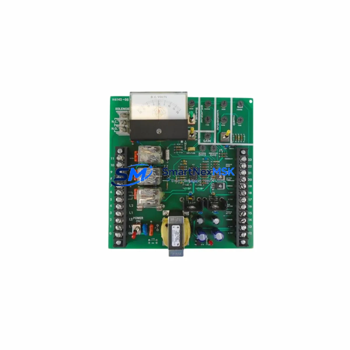
The NORTH AMERICAN H6142-05 is an original DC voltage measurement PC board module engineered for continuous-duty industrial automation environments. As a maintenance-ready spare, the H6142-05 is a critical component in control cabinet upkeep strategies where unplanned downtime carries significant operational and financial risk. Whether you are managing a scheduled overhaul, responding to an emergency fault, or building a strategic spare parts inventory, the H6142-05 delivers verified compatibility, reliable signal accuracy, and a 12-month warranty backed by pre-shipment functional testing.
Maintenance engineers and procurement specialists working with NORTH AMERICAN H6142 series systems recognize that DC voltage measurement integrity is foundational to safe and accurate process control. A degraded or failed H6142-05 module can cascade into erroneous analog readings, nuisance trips, or complete loss of DC bus monitoring — all of which demand immediate corrective action. Stocking a verified replacement eliminates the lead-time risk associated with sourcing obsolete or hard-to-find industrial modules on short notice.
Spare Maintenance Table
| Parameter | Specification / Detail |
|---|---|
| Part Number / SKU | H6142-05 |
| Brand | NORTH AMERICAN |
| Series | H6142 |
| Product Type | DC Voltage Measurement PC Board Module |
| Function | DC voltage signal measurement and conditioning for industrial control systems |
| Compatibility | NORTH AMERICAN H6142 series control panels; compatible with associated DC bus monitoring and analog input circuits |
| Origin | United States (OEM) |
| Installation | PCB board-level replacement; observe ESD precautions and de-energize circuit before installation |
| Application Environment | Industrial control cabinets, automation panels, process control systems |
| Weight | 1,240 g (packaged) |
| Maintenance Recommendation | Inspect signal output accuracy during scheduled PM; replace at first sign of drift or measurement error |
| Pre-Shipment Testing | Functional verification performed before dispatch |
| Warranty | 12 Months |
| Condition | Original spare — new or refurbished to OEM specification |
Maintenance Planning for Continuous Operation
When replacing the H6142-05 DC voltage measurement module, a thorough site inspection of the surrounding electrical circuit is essential to ensure the root cause of failure is addressed and the replacement module is protected from premature damage. Maintenance engineers should treat this replacement as an opportunity for a broader control cabinet audit.
Begin by verifying the DC power supply module feeding the measurement circuit — an unstable or out-of-tolerance supply voltage is a common cause of measurement module failure and must be confirmed within specification before commissioning the replacement H6142-05. Check the input fuse or circuit protection device on the DC bus line; a blown or weakened fuse may indicate a transient overcurrent event that could recur and damage the new module.
Inspect all terminal blocks and wiring connections on the measurement input side. Loose, corroded, or improperly torqued terminals introduce resistance that distorts DC voltage readings and accelerates board-level wear. If the H6142 series panel includes a signal isolator or signal conditioner between the field sensor and the measurement module, verify its output range and calibration — a drifting isolator can mimic a failed measurement board and should be replaced concurrently if its service life is uncertain.
For systems where the H6142-05 feeds analog data to a PLC analog input module or a DCS analog input card, confirm that the receiving channel is reading correctly after replacement. Cross-check the engineering unit scaling and zero/span calibration in the controller configuration. If the panel includes an HMI display or operator panel showing DC voltage values, verify that the displayed readings match the calibrated reference after the new module is installed.
Where the H6142 series system includes relay output modules or protection relays that act on DC voltage thresholds, test their trip setpoints after the measurement module replacement to confirm correct system response. Also inspect any communication modules (such as Modbus RTU or PROFIBUS interface cards) that may transmit DC bus data upstream — ensure their diagnostic registers reflect accurate values post-replacement.
Finally, review the backplane or rack assembly for signs of heat damage, contamination, or mechanical stress that may have contributed to the original failure. A proactive inspection of adjacent board slots and connector integrity reduces the risk of repeat failures and extends the service life of the entire H6142 series panel.
Site Replacement Workflow
Step 1 — Isolation & Safety: De-energize the control panel and verify zero voltage on the DC bus using a calibrated multimeter. Lock out / tag out (LOTO) per site safety procedures before opening the cabinet.
Step 2 — Documentation: Photograph the existing H6142-05 installation, including wiring, connector orientation, and any jumper or DIP switch settings. Record the current measurement readings from the HMI or SCADA system for post-replacement comparison.
Step 3 — Module Removal: Carefully disconnect all signal and power connectors from the H6142-05 board. Use ESD-safe handling procedures. Remove the board from its mounting position and inspect the connector pins and PCB for visible damage or burn marks.
Step 4 — Replacement Installation: Install the new H6142-05 module, ensuring all connectors are fully seated and terminal screws are torqued to specification. Replicate any jumper or configuration settings from the original board as documented in Step 2.
Step 5 — Power-Up & Verification: Re-energize the panel in a controlled sequence. Verify DC voltage measurement output against a known reference. Confirm correct readings on the HMI and in the PLC/DCS analog input channel. Check for any fault or alarm indications in the controller diagnostic log.
Step 6 — System Return to Service: Document the replacement in the maintenance management system (CMMS), update the spare parts inventory record, and note the 12-month warranty start date. Schedule a follow-up inspection at the next planned PM interval to confirm sustained measurement accuracy.
Spare Parts Support FAQ
Q1: Is the H6142-05 compatible with all variants in the NORTH AMERICAN H6142 series panel?
The H6142-05 is designed as a direct replacement within the H6142 series. Compatibility should be confirmed against the original panel documentation and wiring diagram. If you are unsure, contact our technical team with your panel model number and we will verify fit before shipment.
Q2: What pre-shipment testing is performed on the H6142-05?
Each H6142-05 unit undergoes functional verification prior to dispatch, including DC voltage measurement output checks and connector integrity inspection. Units are packaged with ESD-protective materials to ensure safe transit to site.
Q3: How should I manage H6142-05 inventory for long-term system support?
For facilities operating multiple H6142 series panels or systems with extended service life requirements, we recommend maintaining at least one H6142-05 spare on-site. Given the obsolescence risk associated with legacy industrial modules, securing a small buffer stock significantly reduces emergency procurement lead times and protects against production downtime.
Q4: What does the 12-month warranty cover?
The 12-month warranty covers manufacturing defects and functional failures under normal operating conditions. It does not cover damage resulting from incorrect installation, overvoltage events, or failure to follow ESD handling procedures. Warranty claims are supported with replacement or repair at no additional cost within the warranty period.
© 2026 SMARTNEXMSK. All rights reserved.
Original Source: https://smartnexmsk.com
Contact: sales@smartnexmsk.com | +86 18259474341