OPTILOGTC OL2109 Maintenance-Ready Spare for Optimation Automation
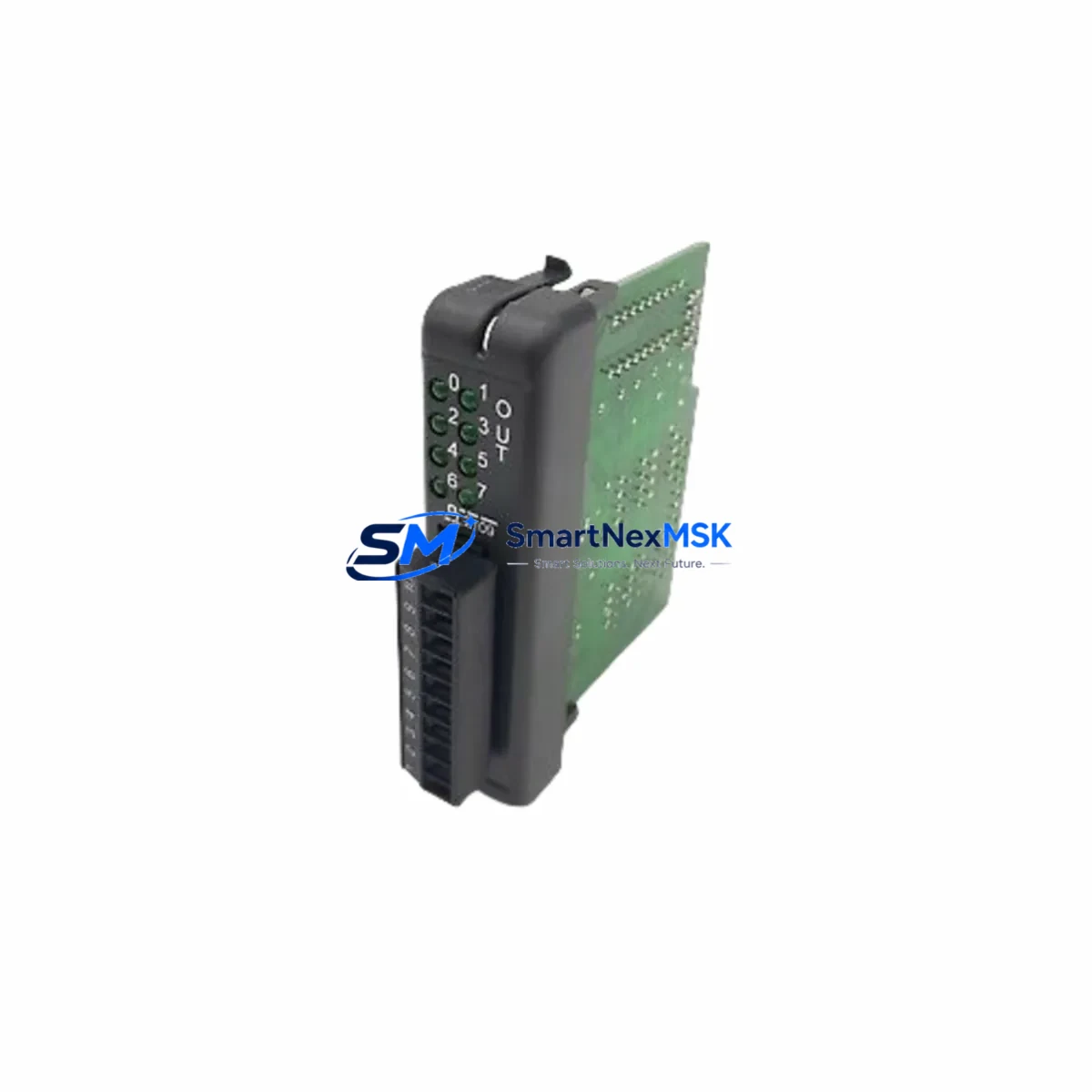
The OPTILOGTC OL2109 is an original digital output (DO) module designed for the Optimation Series distributed control and automation platform. For maintenance engineers managing aging control systems, the OL2109 represents a critical spare that directly governs field-side switching of actuators, solenoid valves, motor starters, and relay-driven loads. Sourcing a verified original replacement — not a counterfeit or grey-market substitute — is the single most important step in reducing unplanned downtime and restoring system integrity after a DO module failure.
At SMARTNEXMSK, every OL2109 unit is sourced through authorized supply channels, inspected prior to dispatch, and shipped with a 12-month warranty covering manufacturing defects and functional failure under normal operating conditions. We maintain buffer stock specifically for Optimation Series components to support both emergency callouts and planned maintenance schedules.
Spare Maintenance Table
| Parameter | Specification / Detail |
|---|---|
| Part Number / SKU | OL2109 |
| Brand | OPTILOGTC |
| Series | Optimation |
| Module Type | Digital Output (DO) Module |
| Output Channels | Typically 8–16 discrete output channels (per Optimation Series standard) |
| Output Type | Relay / Transistor (confirm with system documentation) |
| Supply Voltage | 24 VDC nominal (verify against panel drawing) |
| Load Capacity | Per channel rating per Optimation Series datasheet |
| Backplane Compatibility | Optimation Series rack / backplane |
| Installation | Hot-swap capable (verify with system integrator); DIN rail / rack mount |
| Operating Temperature | 0°C to 55°C (industrial ambient) |
| Origin | CN (manufactured / sourced) |
| Weight | 1,230 g |
| Condition | Original, new / surplus stock |
| Warranty | 12 Months — covers manufacturing defects and functional failure |
| Lead Time | In-stock: ships within 1–3 business days |
| Testing | Pre-shipment functional verification |
Maintenance Planning for Continuous Operation
A digital output module failure rarely occurs in isolation. When the OL2109 is flagged during a fault diagnostic or routine panel inspection, experienced maintenance engineers know to audit the surrounding electrical circuit before committing to a single-component swap. The following components should be checked as part of a structured replacement workflow:
Begin with the 24 VDC power supply module feeding the DO rack — an under-voltage or ripple condition is a common root cause of premature output module degradation. Verify the backplane or rack bus connector for oxidation or mechanical damage, as poor backplane contact can cause intermittent channel faults that mimic module failure. Inspect the field-side terminal blocks and wiring harness connected to the OL2109 output channels; loose terminations or insulation breakdown can cause overcurrent events that stress output drivers.
If the OL2109 drives relay-controlled loads, check the interposing relay modules (such as Optimation Series relay output cards or equivalent DIN-rail relay bases) for contact wear or coil failure. For systems using digital input (DI) modules in the same rack — such as the OL2108 or equivalent Optimation DI cards — verify that feedback signals from field devices are being received correctly, as a failed DO channel may be masked by a corresponding DI fault.
Review the communications module or CPU backplane interface to confirm that the controller is correctly addressing the OL2109 slot. In Optimation Series architectures, a misconfigured I/O map after a module swap is a common commissioning error. If the system uses a signal isolator or surge protection barrier on high-risk output channels (motor starters, solenoid valves in hazardous areas), inspect these barriers for blown protection elements.
For panels with an HMI or operator panel connected to the same controller, confirm that output status displays are updating correctly after the module replacement — this validates both the hardware swap and the software I/O configuration. Finally, check the system fuse or circuit breaker protecting the DO module’s field power rail; a blown fuse is often the first indicator of an output channel short that may have damaged the OL2109 in the first place.
Maintaining a minimum of one OL2109 spare per control system, alongside matched DI modules, power supply units, and communications cards, is the recommended strategy for facilities operating Optimation Series platforms beyond their original design life.
Site Replacement Workflow
Step 1 — Isolate and document. Before removing the failed OL2109, record the current I/O configuration, channel assignments, and wiring labels. Photograph the terminal connections if field wiring is not clearly documented in the panel drawings.
Step 2 — Power down the field circuit. De-energize the 24 VDC field power rail supplying the DO module. Do not rely solely on the controller’s software disable — physically isolate the field power to prevent arc flash or unintended actuator movement during the swap.
Step 3 — Remove and inspect. Extract the OL2109 from the backplane. Inspect the backplane connector pins for damage. If pins are bent or corroded, clean or replace the backplane connector before installing the new module.
Step 4 — Install the replacement OL2109. Seat the new module firmly into the backplane slot. Reconnect field wiring per the original terminal documentation. Verify torque on all terminal screws.
Step 5 — Restore power and verify. Re-energize the field power rail. From the HMI or engineering workstation, force each output channel ON/OFF and confirm correct field-side response. Check for any fault LEDs on the module front panel.
Step 6 — Update maintenance records. Log the replacement date, module serial number, and any observations about the failed unit. Return the failed OL2109 for failure analysis if root cause investigation is required.
This workflow minimizes re-work risk and ensures the replacement OL2109 is fully validated before the system is returned to automatic operation. SMARTNEXMSK ships all OL2109 units with pre-shipment test documentation to support your incoming inspection process.
Spare Parts Support FAQ
Q1: Is the OL2109 a direct drop-in replacement for the original Optimation Series module?
Yes. The OL2109 supplied by SMARTNEXMSK is an original OPTILOGTC part manufactured to the same specification as the unit installed in your system. No firmware changes or hardware modifications are required for a like-for-like swap in a compatible Optimation Series rack.
Q2: What does the 12-month warranty cover?
The warranty covers manufacturing defects and functional failure under normal industrial operating conditions for 12 months from the date of shipment. It does not cover damage caused by incorrect installation, overvoltage events, or physical mishandling. SMARTNEXMSK provides pre-shipment functional test documentation with each unit.
Q3: How do I verify compatibility before ordering?
Provide your system’s rack model, backplane revision, and controller firmware version when placing your order. Our technical team will cross-reference your configuration against the OL2109 compatibility matrix and confirm fit before dispatch. We can also advise on any known revision differences between OL2109 production batches.
Q4: Can SMARTNEXMSK support long-term or blanket spare parts orders for Optimation Series systems?
Yes. We offer scheduled delivery agreements and buffer stock reservation for customers managing multiple Optimation Series installations or operating under planned maintenance contracts. Contact our sales team to discuss volume pricing, lead time guarantees, and multi-SKU spare kits covering DO modules, DI modules, power supplies, and communications cards.
© 2026 SMARTNEXMSK. All rights reserved.
Original Source: https://smartnexmsk.com
Contact: sales@smartnexmsk.com | +86 18259474341