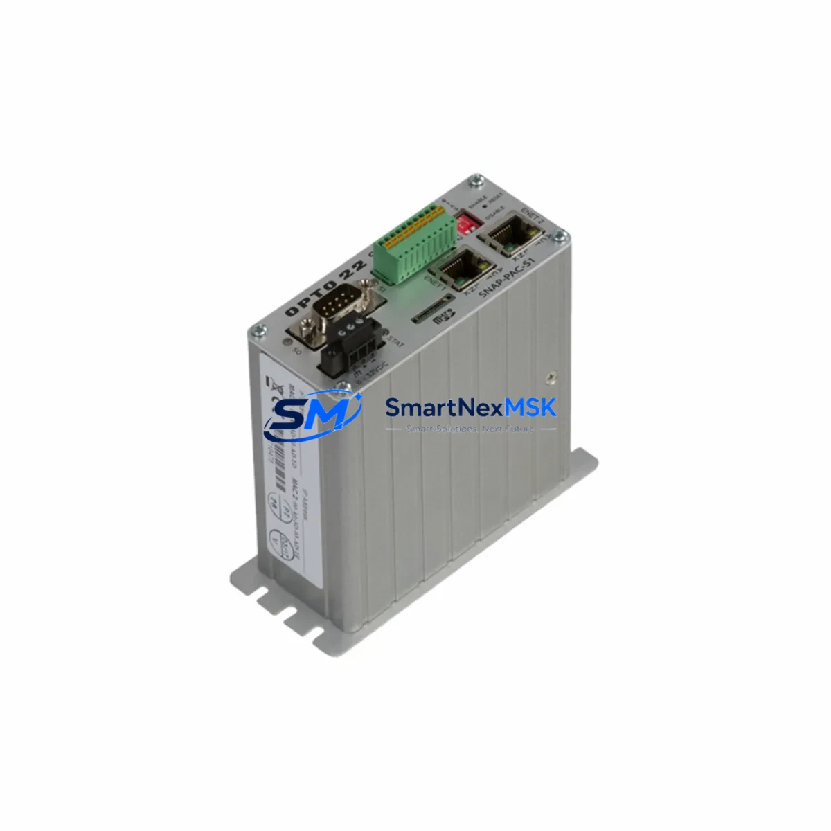
OPTO22 SNAP-PAC-S1 Maintenance-Ready Spare PAC Series Automation
The OPTO22 SNAP-PAC-S1 is a standalone Programmable Automation Controller (PAC) designed for demanding industrial environments where uptime is non-negotiable. As a maintenance-ready original spare, this unit supports rapid field replacement in SNAP PAC Series control architectures, enabling maintenance engineers to restore system operation with minimal downtime. Whether you are managing a scheduled overhaul, responding to an unplanned fault, or building a strategic spare parts inventory for a critical production line, the SNAP-PAC-S1 delivers the compatibility, reliability, and long-term supply assurance that industrial operations require.
The SNAP-PAC-S1 integrates a 32-bit processor with onboard Ethernet, serial communications, and support for OPTO22’s SNAP I/O subsystem. It runs PAC Control and PAC Display software natively, making it a direct drop-in replacement for aging or failed controllers in existing PAC Series installations. For maintenance teams managing legacy automation systems, this means no re-engineering of control logic, no reconfiguration of I/O maps, and no retraining of operators — simply swap, restore the program, verify communications, and return to production.
Every unit shipped from our inventory undergoes functional verification and burn-in testing prior to dispatch. All SNAP-PAC-S1 spares are covered by a 12-month warranty from the date of shipment, providing procurement engineers with the confidence needed to justify spare parts investment to plant management.
Spare Maintenance Table
| Parameter | Specification |
|---|---|
| SKU / Part Number | SNAP-PAC-S1 |
| Brand | OPTO22 |
| Series | SNAP PAC Series |
| Product Type | Programmable Automation Controller (PAC) |
| Processor | 32-bit, 333 MHz |
| Memory | 64 MB RAM / 32 MB Flash |
| Communication Ports | 2× Ethernet 10/100 Mbps, 1× RS-232, 1× RS-485 |
| I/O Compatibility | SNAP PAC I/O Modules (analog, digital, serial) |
| Operating Voltage | 10–32 VDC |
| Operating Temperature | 0°C to 70°C |
| Mounting | DIN rail or panel mount via SNAP PAC rack |
| Software Compatibility | PAC Control, PAC Display, PAC Manager |
| Origin | USA |
| Warranty | 12 Months from shipment date |
| Pre-shipment Testing | Functional verification and burn-in completed |
| Replacement Compatibility | Direct replacement for SNAP-PAC-S1, compatible with SNAP-PAC-S2 rack configurations |
Maintenance Planning for Continuous Operation
When a SNAP-PAC-S1 controller is identified as the root cause of a system fault or is flagged during a planned inspection cycle, experienced maintenance engineers know that replacing the controller alone is rarely sufficient for a complete and reliable recovery. A thorough site assessment should accompany every PAC replacement to prevent repeat failures and ensure the restored system meets its original design specification.
Begin by inspecting the SNAP PAC rack and backplane for signs of corrosion, loose seating, or mechanical damage. The rack is the physical and electrical backbone of the SNAP I/O subsystem, and any degradation here will affect the replacement controller’s ability to communicate reliably with field devices. Next, verify the 24 VDC power supply feeding the controller and I/O rack — an undersized or aging power supply is a common contributor to intermittent PAC faults and should be load-tested before the new unit is commissioned.
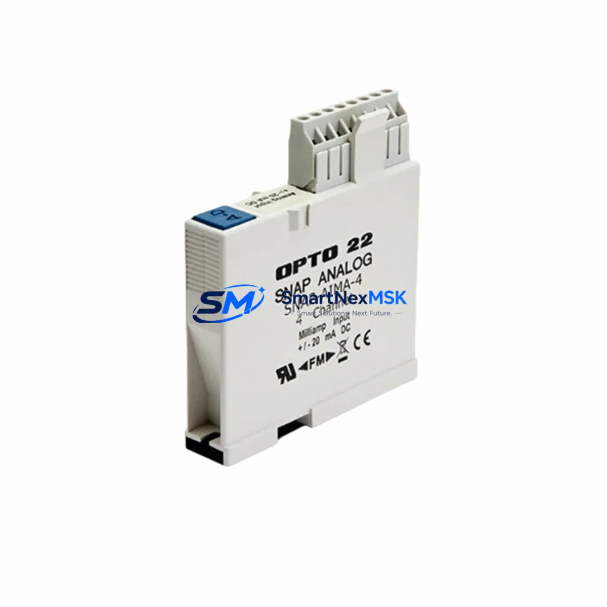
Inspect all SNAP digital input and output modules installed in the rack. Modules such as the SNAP-IDC5 (digital input) and SNAP-ODC5 (digital output) are subject to wear from switching cycles and should be checked for response time degradation or channel failures. Similarly, SNAP analog input modules (e.g., SNAP-AIMA-4 or SNAP-AIV) should be verified for signal accuracy against known reference values before the system is returned to automatic control.
Review the Ethernet network infrastructure connecting the SNAP-PAC-S1 to SCADA, HMI, and peer controllers. Faulty patch cables, degraded managed switches, or misconfigured IP settings are frequent causes of communication loss that can be misdiagnosed as controller failure. If the installation uses serial communications via RS-232 or RS-485, inspect the SNAP-SCM-232 or SNAP-SCM-485 serial communication modules for correct termination and signal integrity.
For installations that include PAC Display HMI workstations, confirm that the HMI software version is compatible with the replacement controller’s firmware. Firmware mismatches between the SNAP-PAC-S1 and PAC Display can cause tag resolution failures that appear as controller faults. Also verify that any SNAP-PAC-R1 or SNAP-PAC-R2 remote brain units in the system are running compatible firmware and that their I/O maps are intact after the controller swap.
Finally, check all terminal blocks and field wiring connected to the I/O modules. Loose terminations, corroded conductors, or incorrectly rated fuses in the control cabinet are often discovered during a PAC replacement and should be corrected before the system is re-energized. Maintaining a documented spare parts list that includes the SNAP-PAC-S1 alongside associated power supplies, I/O modules, communication modules, and network components is the most effective strategy for minimizing mean time to repair (MTTR) across the facility.
Site Replacement Workflow
Step 1 — Isolate and document: Place the affected control loop in manual or safe state. Record the current controller firmware version, IP address configuration, and PAC Control strategy file version from PAC Manager before powering down.
Step 2 — Physical removal: Disconnect Ethernet cables, serial connections, and the DC power feed. Remove the SNAP-PAC-S1 from the rack, noting the slot position and any jumper settings on the unit.
Step 3 — Inspect the rack and power supply: Before installing the replacement, verify rack integrity and measure the DC supply voltage under load. Address any anomalies before proceeding.
Step 4 — Install the replacement SNAP-PAC-S1: Seat the new controller firmly in the rack. Reconnect power, Ethernet, and serial cables. Apply power and confirm the unit boots to a healthy state via the front-panel status LEDs.
Step 5 — Restore configuration: Use PAC Manager to assign the correct IP address and hostname. Download the saved PAC Control strategy file to the controller. Verify all I/O module communications are established and that analog and digital channel values match expected field conditions.
Step 6 — Functional verification: Run the system in manual mode, exercising each output channel and confirming input readings. Obtain sign-off from the responsible engineer before returning to automatic control.
This workflow is compatible with both direct SNAP-PAC-S1 replacements and cross-upgrades from older SNAP-PAC-S1 units to current production firmware, ensuring system continuity without requiring re-engineering of the control strategy.
Spare Parts Support FAQ
Q1: Is this SNAP-PAC-S1 an original OPTO22 unit or a third-party compatible?
This is an original OPTO22 SNAP-PAC-S1 sourced directly from authorized supply channels. It is not a clone, refurbished third-party unit, or compatible substitute. The unit carries the full OPTO22 part number and is covered by our 12-month warranty from the date of shipment.
Q2: How do I verify compatibility with my existing SNAP PAC installation before ordering?
The SNAP-PAC-S1 is compatible with all standard SNAP PAC racks and SNAP I/O modules. Confirm your existing rack model (e.g., SNAP-PAC-R1, SNAP-PAC-R2, or SNAP-PAC-EB1) and the PAC Control strategy version in use. If your installation uses a specific firmware version, contact us with your current firmware revision and we will confirm compatibility before shipment.
Q3: What pre-shipment testing is performed on each unit?
Every SNAP-PAC-S1 unit undergoes functional power-on verification, communication port testing (Ethernet and serial), and I/O subsystem communication checks prior to dispatch. A test report is available upon request. Units that do not pass all verification steps are not shipped.
Q4: What is the recommended spare parts strategy for a facility running multiple SNAP PAC systems?
For facilities with three or more SNAP PAC controllers, we recommend maintaining at least one SNAP-PAC-S1 as a cold spare per production zone, alongside spares for the most frequently replaced I/O modules (digital input, digital output, and analog input). Pairing the controller spare with a spare 24 VDC power supply and a set of SNAP serial communication modules ensures that the most common failure modes can be addressed within a single maintenance shift without waiting for emergency procurement.
© 2026 SMARTNEXMSK. All rights reserved.
Original Source: https://smartnexmsk.com
Contact: sales@smartnexmsk.com | +86 18259474341