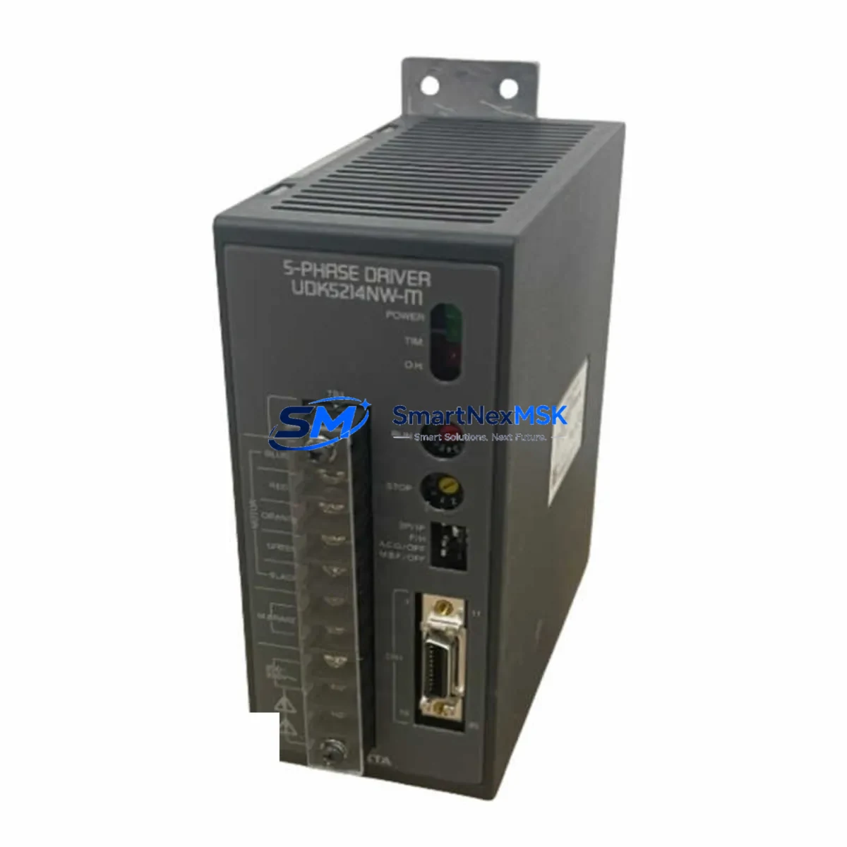
Oriental Motor UDK5214NW-M Maintenance-Ready Spare UDK5 Automation
The Oriental Motor UDK5214NW-M is a 5-phase microstepping driver from the UDK5 Series, engineered for precision motion control in industrial automation environments. As a maintenance-ready original spare, this unit is sourced, inspected, and dispatched to support rapid replacement in production lines, packaging machinery, semiconductor handling equipment, and multi-axis positioning systems where unplanned downtime carries significant operational cost.
For maintenance engineers managing aging automation infrastructure, the UDK5214NW-M represents a direct, specification-matched replacement for worn or failed drivers in UDK5-based motion control cabinets. Its compatibility with Oriental Motor’s 5-phase stepper motor families — including the PK Series and RK Series — means no re-parameterization of pulse input logic is required when swapping units in the field. The driver accepts standard step/direction or CW/CCW pulse signals, making integration with existing PLC ladder programs and motion controllers straightforward.
Procurement engineers sourcing this unit for planned maintenance or emergency stock replenishment can rely on our SKU-verified inventory process: every UDK5214NW-M is cross-checked against the manufacturer part number before dispatch, reducing the risk of receiving a mismatched or counterfeit component in a critical spare parts order.
Spare Maintenance Table
| Parameter | Specification |
|---|---|
| Part Number / SKU | UDK5214NW-M |
| Brand | Oriental Motor |
| Series | UDK5 (5-Phase Stepper Driver) |
| Drive Type | 5-Phase Microstepping Driver |
| Input Voltage | 100–120 VAC / 200–240 VAC, Single Phase |
| Output Current | Up to 2.1 A/phase (peak) |
| Step Resolution | Full step to 1/250 microstep (selectable) |
| Control Input | Step/Direction or CW/CCW pulse signal |
| Compatible Motors | Oriental Motor 5-phase stepper motors (PK, RK Series) |
| Mounting | DIN rail or panel mount |
| Operating Temperature | 0°C to +50°C |
| Storage Temperature | -20°C to +70°C |
| Protection Class | IP20 (control cabinet installation) |
| Origin | Japan |
| Compatibility | Direct replacement for UDK5 Series drivers in existing wiring harness |
| Warranty | 12 Months from date of shipment |
| Condition | Original spare — new or tested-functional |
| Shipping | Tested before dispatch; worldwide express available |
Maintenance Planning for Continuous Operation
When a UDK5214NW-M driver fails or is flagged during a scheduled inspection, experienced maintenance engineers know that the driver itself is rarely the only component requiring attention. A thorough site assessment during the replacement window should include the following checks to prevent repeat failures and maximize the value of the planned downtime:
Power supply integrity: Verify the 24 VDC control power supply feeding the driver’s logic circuit. A degraded switching power supply — such as a Meanwell or Omron S8VS series unit — can cause intermittent driver faults that mimic motor or encoder issues. Measure output voltage under load before reinstalling the replacement driver.
Motor cable and connector condition: Inspect the 5-phase motor cable connecting the UDK5214NW-M to the stepper motor. Cracked insulation, loose crimp terminals, or corroded D-sub connectors are common causes of phase-loss faults. Replace the motor cable assembly if any wear is detected — using a matched Oriental Motor cable ensures correct phase sequencing without rewiring.
I/O signal wiring: Check the pulse input wiring from the upstream motion controller or PLC output module. Verify that the step/direction signals meet the driver’s input voltage and frequency specifications. Noise on the signal line — often introduced by proximity to high-current servo cables — can cause missed steps or erratic motion. Installing a signal isolator or ferrite core on the pulse line is a low-cost preventive measure.
Protective fuses and circuit breakers: Inspect the branch circuit fuse or miniature circuit breaker (MCB) protecting the driver’s AC input. A fuse that has operated at the margin of its rating may have degraded and should be replaced as a matter of course during the maintenance window.
Terminal blocks and grounding: Loose terminal block connections on the driver’s AC input or motor output terminals are a frequent source of intermittent faults in vibration-prone environments. Torque all terminals to specification and verify that the protective earth (PE) connection is secure. Phoenix Contact or Weidmüller terminal blocks used in the same cabinet should be inspected for discoloration or heat damage.
Communication and controller interface: If the UDK5214NW-M is controlled via a PLC output module — such as a Mitsubishi QY40P or Omron CJ1W-OD211 transistor output card — verify that the output module’s sink/source configuration matches the driver’s input polarity. A misconfigured output module can prevent the driver from accepting pulse commands after replacement.
Adjacent relay and contactor condition: Inspect any interposing relays or contactors in the driver’s enable or alarm circuit. Relay contacts that have pitted or welded can prevent the driver from entering run mode or clearing fault states after power cycling.
HMI and operator panel: If the machine uses a Proface GP or Keyence VT Series HMI to display driver status or alarm codes, verify that the HMI communication link to the PLC is functioning correctly after the driver swap. A stale alarm state on the HMI can cause operators to believe the replacement has failed when the driver is actually operating normally.
Addressing these surrounding components during the same maintenance window — rather than treating the UDK5214NW-M as an isolated replacement — significantly reduces the probability of a repeat callout and extends the effective service life of the entire motion control assembly.
Site Replacement Workflow
Step 1 — Isolate and document: De-energize the control cabinet and lock out / tag out (LOTO) the AC supply. Photograph the existing wiring before disconnecting any terminals. Note the DIP switch settings on the outgoing UDK5214NW-M — step resolution, current setting, and input mode — so the replacement unit can be configured identically before installation.
Step 2 — Configure the replacement unit: Set the DIP switches on the new UDK5214NW-M to match the documented settings from the outgoing driver. Do not power the unit before configuration is complete. Verify that the motor type selection matches the connected 5-phase stepper motor.
Step 3 — Reconnect and verify: Reconnect the AC input, motor cable, and signal wiring. Confirm that the protective earth is connected before energizing. Apply power and observe the driver’s LED status indicators — a steady green RUN indicator confirms normal operation. Issue a low-speed jog command from the PLC or motion controller to verify motor response before returning the axis to automatic mode.
Step 4 — Functional test: Run the axis through its full travel range at reduced speed to confirm smooth motion and correct limit switch operation. Check for any vibration or noise that could indicate a phase wiring error. Log the replacement in the maintenance management system (CMMS) with the new unit’s serial number and installation date.
Step 5 — Update spare parts inventory: Record the consumption of the UDK5214NW-M from the spare parts store and initiate a replenishment order to restore the minimum stock level. For high-utilization lines, maintaining at least one additional unit on the shelf eliminates the risk of a second failure causing extended downtime while awaiting delivery.
Spare Parts Support FAQ
Q1: What is the expected service life of the UDK5214NW-M, and when should I plan a proactive replacement?
The UDK5 Series drivers are designed for long service life under normal operating conditions, but electrolytic capacitors in the power stage typically begin to degrade after 7–10 years of continuous operation. For systems approaching this age, proactive replacement during a scheduled shutdown — rather than waiting for a failure — is the recommended strategy. Keeping one spare unit in stock ensures the replacement can be executed within the planned maintenance window without expedited freight costs.
Q2: How do I verify compatibility before installing the UDK5214NW-M as a replacement for an older UDK5 Series driver?
Confirm that the replacement unit’s input voltage range matches the site supply (100–120 VAC or 200–240 VAC), that the output current rating is appropriate for the connected motor, and that the physical connector layout matches the existing wiring harness. The UDK5214NW-M is designed as a direct form-fit-function replacement within the UDK5 Series, so no modifications to the motor cable or signal wiring should be required. If the outgoing unit is a different model within the series, compare the DIP switch function tables in the respective datasheets before proceeding.
Q3: What pre-shipment testing is performed on the UDK5214NW-M before dispatch?
Every unit is verified against the manufacturer part number (UDK5214NW-M) before packing. Functional units are powered and checked for correct LED status indication. Units are packed in anti-static packaging with physical protection to prevent transit damage. A 12-month warranty from the date of shipment covers any manufacturing defects or functional failures that emerge under normal operating conditions.
Q4: Can you support long-term or blanket orders for the UDK5214NW-M for ongoing maintenance programs?
Yes. For maintenance teams managing multiple machines or sites with UDK5-based motion control, we support scheduled delivery programs and can reserve stock against a forward purchase commitment. This approach eliminates the risk of supply gaps caused by market shortages of legacy stepper driver models and allows procurement teams to lock in pricing for budget planning purposes. Contact our sales team to discuss your annual consumption requirements.
© 2026 SMARTNEXMSK. All rights reserved.
Original Source: https://smartnexmsk.com
Contact: sales@smartnexmsk.com | +86 18259474341