OXFORD TL4 1128-426 Retrofit-Ready PCI Communication Card for TL4 Series Control Systems
The OXFORD TL4 1128-426 is a retrofit-ready PCI communication card engineered for seamless integration into TL4 Series industrial control systems. As legacy automation infrastructure ages and original spare parts become increasingly difficult to source, the TL4 1128-426 provides a reliable, tested, and immediately available replacement solution for plant engineers and system integrators managing aging control cabinets. Whether you are executing a planned system upgrade, responding to an unplanned card failure, or migrating a legacy control platform to a modern architecture, this module is designed to minimize engineering risk and reduce total downtime.
Sourced directly from verified supply channels and subjected to full functional testing prior to shipment, each unit is backed by a 12-month warranty and ships from our Xiamen warehouse. Our team supports customers through the full retrofit lifecycle — from pre-installation compatibility verification to post-commissioning technical review.
Upgrade Compatibility Table
| Parameter | Details |
|---|---|
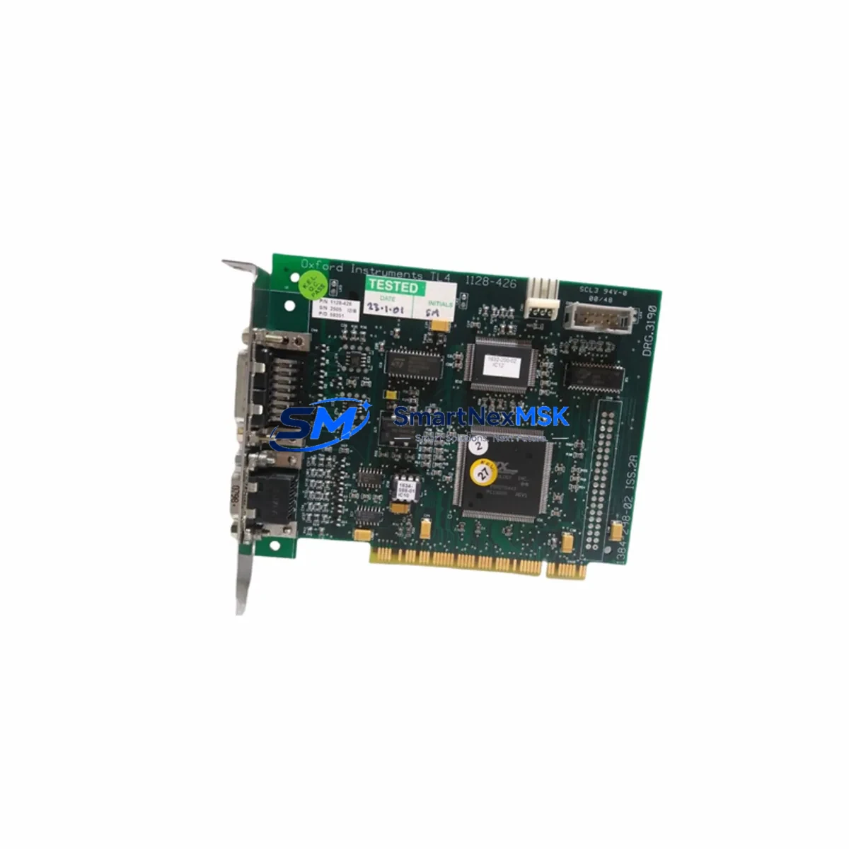
| Module Model | OXFORD TL4 1128-426 |
| Form Factor | PCI Bus Card |
| Series Compatibility | TL4 Series Control Systems |
| Installation Interface | Standard PCI Slot (32-bit, 33 MHz) |
| Communication Protocol | TL4 Series native protocol; verify host controller firmware version before installation |
| Replacement Scope | Direct drop-in for discontinued TL4 1128-426 OEM cards |
| Backplane Compatibility | Confirm rack slot assignment and backplane revision with existing system documentation |
| Commissioning Requirement | Address configuration via system software; no hardware jumper changes required in standard retrofit |
| Warranty | 12 Months — covers functional defects under normal operating conditions |
| Origin | China (CN) — exported with full documentation |
Retrofit Planning for Existing Automation Systems
Successful retrofit of the TL4 1128-426 begins well before the card is physically installed. Engineers should start by auditing the existing control cabinet layout, confirming available PCI slot positions in the host rack, and reviewing the backplane revision to ensure mechanical and electrical compatibility. In many TL4-based installations, the communication card works in conjunction with a dedicated TL4 Series CPU module and one or more TL4 I/O expansion modules — both of which should be inspected for firmware currency before the new card is commissioned.
Power budget verification is a critical pre-installation step. The host system’s 24VDC power supply module must have sufficient headroom to support the TL4 1128-426 alongside existing loads. In older control cabinets where the power supply has been running at or near capacity, this is a common source of post-installation instability. If the existing supply is marginal, a parallel or replacement TL4-compatible power supply unit should be staged before the retrofit window opens.
Terminal wiring should be documented in full before any module is removed. Photograph or export the existing wiring diagram from the engineering workstation, and verify that the field wiring connected to adjacent TL4 digital input modules and TL4 analog output modules will not be disturbed during the card swap. In systems where the communication card interfaces with a PROFIBUS DP network or Modbus RTU link, the network segment must be placed in a safe state and the master controller notified before the card is removed.
For systems that include an operator HMI panel linked to the TL4 controller via the communication card, the HMI screen logic and tag bindings should be exported and backed up prior to the retrofit. After the new TL4 1128-426 is installed and the system is powered on, HMI communication should be re-established and all active screen tags verified against the original configuration. In some installations, a programming cable (typically USB-to-serial or RS-232) connected to the CPU module’s programming port will be required to reload or verify the resident control program before the system is returned to automatic mode.
Module address assignment is another area that requires careful attention. In rack-based TL4 architectures, each module occupies a defined slot address that is referenced in the PLC program. If the TL4 1128-426 is being installed into a slot previously occupied by a different card type, the program logic must be reviewed to confirm that no address conflicts exist. This review should be performed in the offline project file before the system is powered down for the swap.
Downtime Control During System Migration
Minimizing production downtime during a TL4 communication card replacement requires a structured pre-outage preparation protocol. All configuration data — including the resident program, I/O mapping tables, communication parameters, and HMI tag databases — should be exported and stored on a secure engineering laptop before the maintenance window begins. Where possible, a cold spare of the TL4 1128-426 should be pre-staged and pre-tested on a bench setup to confirm it powers on and initializes correctly before the live system is touched.
During the physical swap, the control system should be placed in a defined safe state: field outputs de-energized, interlocks confirmed, and the operator informed. The failed or end-of-life card should be removed carefully, with attention to any retention screws or backplane locking mechanisms specific to the TL4 rack. The replacement TL4 1128-426 should be seated firmly and secured before power is restored.
On power-up, the system should be observed through the first initialization cycle. Communication link status indicators on the card should be checked against the expected state. If the system uses a TL4 Series network switch module or a dedicated communication gateway to bridge legacy and modern network segments, these devices should also be confirmed as online before the controller is released to automatic operation. A structured post-commissioning checklist — covering I/O scan verification, communication link confirmation, HMI screen validation, and a timed observation period under normal load — will ensure that the retrofit is complete and the system is stable before the maintenance window closes.
Retrofit Support FAQ
Q1: Is the OXFORD TL4 1128-426 a direct replacement for the original OEM card?
Yes. The TL4 1128-426 is sourced and tested to match the original OEM specification. It is designed as a drop-in replacement for the same slot position in TL4 Series racks. No hardware modification is required in standard retrofit applications. Customers are advised to confirm the host system’s firmware version and backplane revision prior to installation.
Q2: What commissioning steps are required after installation?
After physical installation, the module address should be verified in the system configuration software. Communication parameters — including baud rate, node address, and protocol settings — should be confirmed against the original card’s configuration record. If a programming cable is required to reload or verify the resident program, this should be performed before the system is returned to automatic mode. Our technical team can provide commissioning guidance on request.
Q3: How is wiring compatibility handled during the card swap?
The TL4 1128-426 uses standard PCI bus interface for backplane communication; field wiring is not directly terminated on this card. However, any field devices communicating through this card’s network port (e.g., PROFIBUS, Modbus, or proprietary TL4 protocol) must be placed in a safe state before the card is removed. All network cable connections should be labeled and documented before disconnection and restored in the same configuration after the new card is installed.
Q4: What does the 12-month warranty cover?
Each OXFORD TL4 1128-426 unit is covered by a 12-month warranty from the date of shipment. The warranty covers functional defects arising under normal operating conditions, including failure to initialize, communication link faults attributable to the card, and hardware failures not caused by improper installation, overvoltage, or physical damage. Units are fully tested before shipment. Warranty claims are processed through our Xiamen operations team with a target response time of 2 business days.
© 2026 SMARTNEXMSK. All rights reserved.
Original Source: https://smartnexmsk.com
Contact: sales@smartnexmsk.com | +86 18259474341