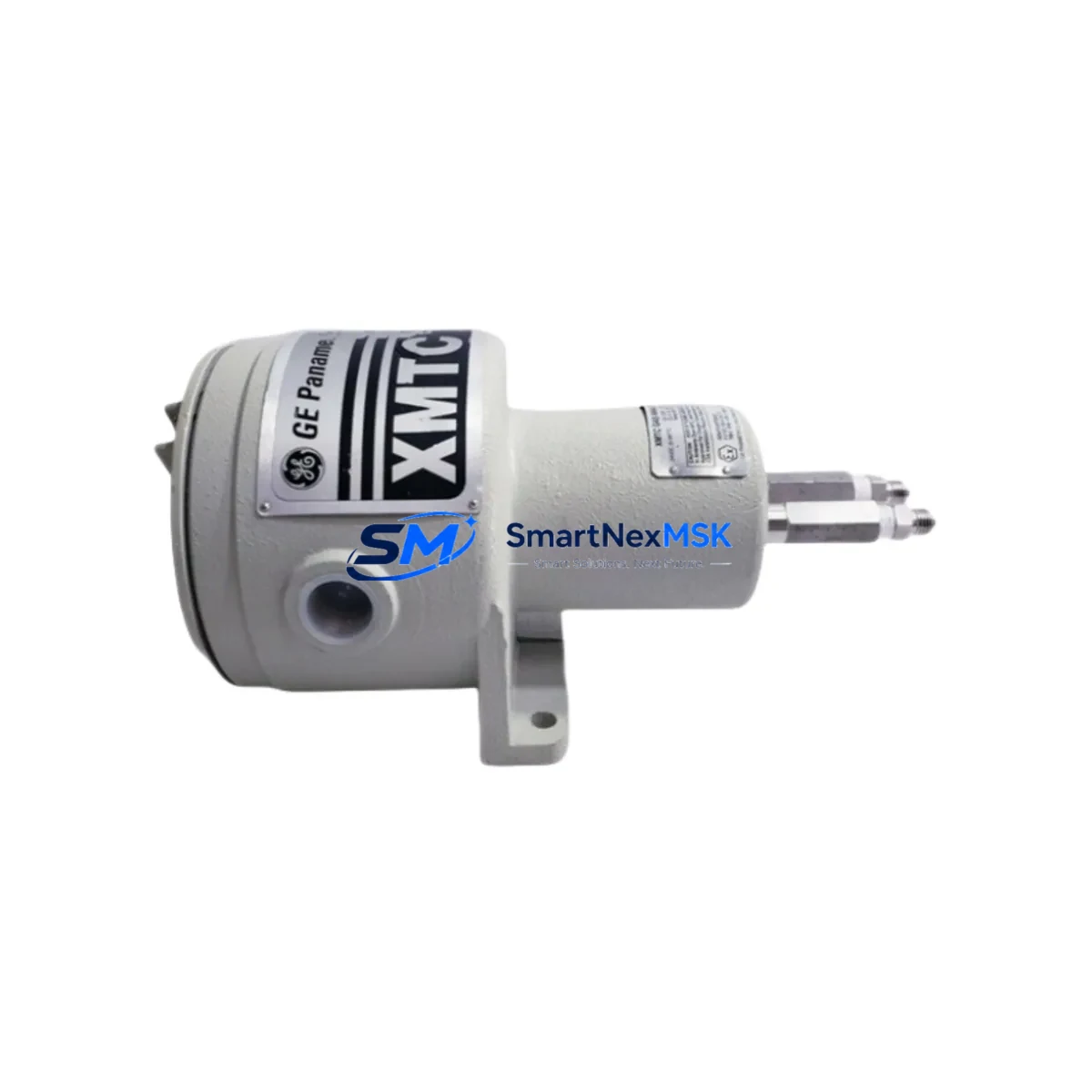
Panametrics XMTC-62-21 Retrofit-Ready Conductivity Transmitter for XMTC Series Control Systems
The Panametrics XMTC-62-21 is a precision conductivity transmitter engineered for seamless integration into existing XMTC Series measurement and control architectures. Whether you are replacing an end-of-life unit on a legacy process line, upgrading a discontinued measurement loop, or restoring a critical analytical control system, the XMTC-62-21 delivers verified electrical and functional compatibility with minimal re-engineering effort. This unit is stocked, tested, and ready to ship — backed by a 12-month warranty.
Industrial facilities operating Panametrics XMTC Series transmitters in water treatment, chemical processing, power generation, and semiconductor manufacturing environments frequently encounter the challenge of sourcing reliable replacement units when original equipment reaches end-of-life. The XMTC-62-21 addresses this directly: it maintains the same signal output range, terminal block layout, and housing form factor as predecessor XMTC models, allowing technicians to execute a controlled swap without modifying existing conduit runs, DCS input cards, or PLC analog input modules.
Upgrade Compatibility Table
| Parameter | XMTC-62-21 (This Unit) | Typical Legacy XMTC Models | Retrofit Notes |
|---|---|---|---|
| Output Signal | 4–20 mA (2-wire) | 4–20 mA (2-wire) | Direct drop-in; no re-ranging required |
| Supply Voltage | 12–36 VDC loop-powered | 12–36 VDC loop-powered | Verify existing power supply capacity before swap |
| Terminal Block | Standard 3-terminal screw block | Standard 3-terminal screw block | Existing field wiring reusable; label before removal |
| Mounting | DIN rail / panel mount | DIN rail / panel mount | Same footprint; no bracket modification needed |
| Communication Protocol | Analog 4–20 mA / HART-compatible | Analog 4–20 mA | HART capability adds diagnostic value; backward compatible |
| Measurement Range | 0–2000 µS/cm (configurable) | Fixed or configurable range | Confirm range setting matches DCS/PLC scaling block |
| Installation Environment | IP65, –10 to +60 °C | IP65 typical | Suitable for control cabinet and field panel installation |
| Warranty | 12-Month Warranty — Covered from date of shipment | ||
Retrofit Planning for Existing Automation Systems
A successful XMTC-62-21 retrofit begins well before the unit arrives on site. Engineers and maintenance teams should audit the existing control cabinet to confirm that the loop power supply — typically a dedicated 24 VDC rail shared with other field instruments — has sufficient residual capacity to support the replacement transmitter. In installations where the original XMTC unit shared a power bus with Panametrics XT Series temperature transmitters or third-party flow transmitters, a load calculation should be performed to prevent nuisance tripping of the supply breaker during commissioning.
Terminal wiring documentation is critical. Before removing the legacy unit, photograph or transcribe the existing terminal assignments. The XMTC-62-21 uses a standard positive supply (+), negative/return (–), and shield/ground terminal arrangement consistent with the broader XMTC product family. If the original installation used a Panametrics XMT Series signal conditioner or a dedicated analog input barrier, verify that the barrier’s input impedance remains within the transmitter’s drive capability — typically 600 Ω maximum loop resistance at 24 VDC supply.
For systems integrated into a Honeywell Experion PKS or Yokogawa CENTUM VP DCS platform, the analog input channel assigned to the legacy XMTC transmitter should be placed in manual mode prior to removal. This prevents the DCS from generating spurious low-signal alarms or triggering interlock logic during the swap window. Similarly, if the conductivity loop feeds a PLC — such as a Siemens S7-300 with a SM 331 analog input module or an Allen-Bradley ControlLogix with a 1756-IF16 card — the corresponding input tag should be forced to a safe value in the ladder logic before disconnecting field wiring.
Backplane and rack considerations are minimal for transmitter-level replacements, but if the XMTC-62-21 is being installed as part of a broader panel upgrade that also involves replacing a Panametrics XMT600 series controller or a legacy signal multiplexer, ensure that the new rack layout preserves the original I/O address mapping. Renumbering analog input channels mid-project is a common source of commissioning delays and should be avoided unless a full program revision is planned.
Where the existing system uses a Modbus RTU or PROFIBUS DP communication backbone — common in older water treatment SCADA architectures — and the XMTC-62-21’s HART output is being leveraged for the first time, a HART-to-Modbus gateway such as a Pepperl+Fuchs WirelessHART adapter or a Emerson 475 Field Communicator can be used to commission and verify the transmitter’s configuration without interrupting the 4–20 mA analog loop. This approach is particularly valuable when the HMI display — whether a Siemens TP700 Comfort Panel or a Weintek cMT Series touchscreen — is configured to display live conductivity values and cannot tolerate a signal interruption during business hours.
For facilities that also need to upgrade associated measurement infrastructure, the XMTC-62-21 is commonly deployed alongside Panametrics XT Series temperature compensation probes, conductivity sensor cells rated for the process fluid, and stainless-steel flow-through sensor housings. In multi-loop installations, a Panametrics XMT868 ultrasonic flow transmitter or a compatible Endress+Hauser Liquiline CM442 multi-parameter transmitter may serve as the primary controller, with the XMTC-62-21 providing a dedicated conductivity measurement channel. All units should be verified against the process P&ID before final installation.
Downtime Control During System Migration
Minimizing unplanned downtime is the primary concern for any control system retrofit. For XMTC-62-21 installations, the recommended approach is a pre-staged swap: the replacement unit is configured, range-checked, and loop-tested on the bench before the scheduled maintenance window. Using a Fluke 789 ProcessMeter or equivalent loop calibrator, technicians can simulate a 4 mA (0% range) and 20 mA (100% range) signal to verify that the DCS or PLC is reading correctly before the new transmitter is connected to the process sensor.
During the physical swap, the existing field wiring should remain connected to the terminal block of the old unit until the new XMTC-62-21 is mounted and ready. A parallel connection — briefly bridging old and new terminals — is not recommended for 2-wire loop-powered devices; instead, the loop should be broken cleanly, the old unit removed, and the new unit connected within the shortest possible window. Total field swap time for an experienced technician is typically under 20 minutes.
After reconnection, the DCS or PLC analog input should be taken out of manual mode and the live reading compared against a reference instrument or process sample. If the system includes a Yokogawa EJA110E differential pressure transmitter or similar reference device on the same process stream, cross-checking the conductivity reading against known process conditions provides a rapid sanity check before returning the loop to automatic control. Original program logic, HMI faceplates, and alarm setpoints require no modification when the XMTC-62-21 is used as a direct replacement — preserving the integrity of the existing control narrative and reducing the risk of operator error during the post-maintenance period.
Retrofit Support FAQ
Q: Is the XMTC-62-21 a direct replacement for all XMTC Series models?
A: The XMTC-62-21 is compatible with the majority of XMTC Series installations sharing the same 4–20 mA loop-powered architecture and terminal block layout. For models with non-standard output ranges or proprietary communication options, contact our technical team to confirm compatibility before ordering. We maintain cross-reference documentation for common XMTC variants.
Q: What wiring checks are required before installation?
A: Verify loop supply voltage (12–36 VDC), total loop resistance (≤600 Ω at 24 VDC), and terminal polarity. Photograph existing terminal connections before removal. Confirm that the shield/ground terminal is bonded to the cabinet earth rail, not the signal return, to avoid ground loop interference on the analog input.
Q: How is the unit tested before shipment?
A: Every XMTC-62-21 unit undergoes a full functional test prior to dispatch, including loop output verification at 4 mA, 12 mA, and 20 mA, insulation resistance check, and housing integrity inspection. A test certificate is available upon request. Units are shipped in anti-static packaging with terminal protection covers installed.
Q: What does the 12-month warranty cover?
A: The 12-month warranty covers manufacturing defects, component failure under normal operating conditions, and output calibration drift beyond published specifications. It does not cover damage resulting from incorrect wiring, overvoltage, or installation in environments exceeding the rated IP65 and temperature specifications. Warranty claims are processed within 5 business days of unit receipt.
© 2026 SMARTNEXMSK. All rights reserved.
Original Source: https://smartnexmsk.com
Contact: sales@smartnexmsk.com | +86 18259474341