Parker Denison 701-00600-8 Spare Gold Cup Automation: Spare Replacement & Industrial Downtime Risk Control
The Parker Denison 701-00600-8 is an original proportional amplifier card designed for Gold Cup hydraulic pump and motor control systems. In industrial automation environments — from steel mills and injection molding lines to marine hydraulic drives and heavy press systems — this amplifier card governs the proportional valve command signal that directly controls flow rate and pressure response. A failed or degraded 701-00600-8 card can result in uncontrolled actuator movement, loss of closed-loop pressure regulation, and unplanned production downtime. Stocking a verified replacement unit is the most effective strategy for minimizing mean time to repair (MTTR) in hydraulic servo and proportional control circuits.
This listing supplies an original-specification 701-00600-8 amplifier card, sourced from authorized channels, individually tested prior to shipment, and backed by a 12-month warranty. Each unit is verified for signal output linearity, enable logic response, and compatibility with Gold Cup Series 7 and Series 9 variable-displacement piston pump control assemblies. Whether you are executing a planned overhaul, responding to an emergency fault, or building a critical-spare inventory for a multi-press facility, this card ships ready for direct installation.
Spare Maintenance Table
| Parameter | Specification / Detail |
|---|---|
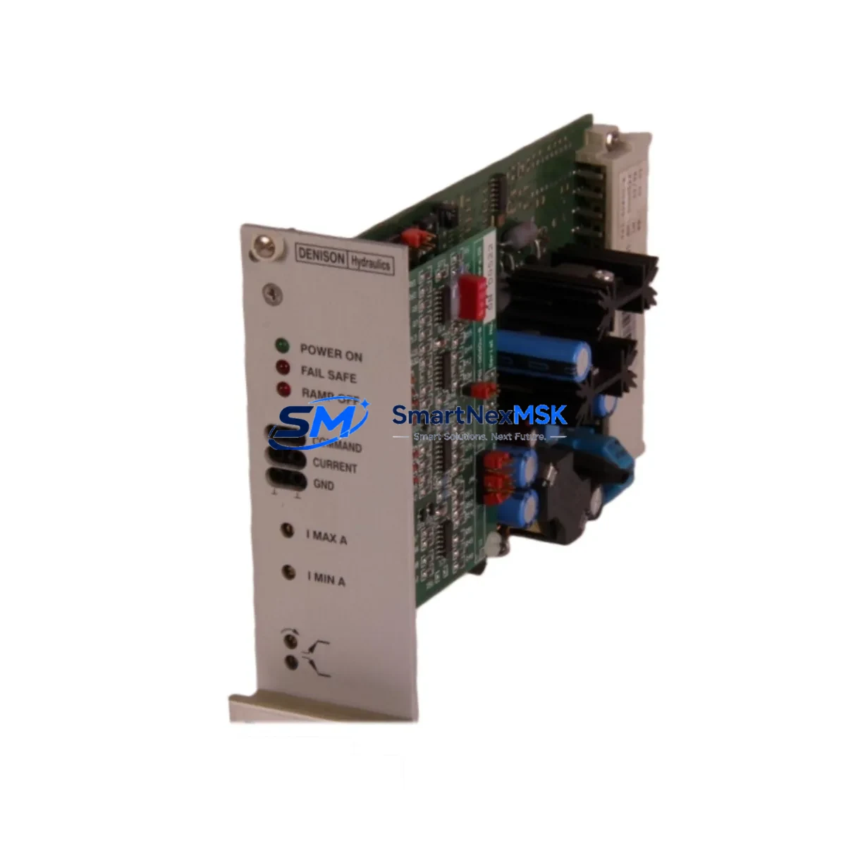
| Part Number | 701-00600-8 |
| Brand | Parker Denison Hydraulics |
| Series Compatibility | Gold Cup Series 7 / Series 9 Hydraulic Pump & Motor Controls |
| Component Type | Proportional Amplifier Card |
| Input Signal | ±10 VDC command reference (proportional valve interface) |
| Output | Proportional solenoid drive current, adjustable gain & ramp |
| Supply Voltage | 24 VDC nominal (±15% tolerance) |
| Enable Logic | Digital enable input, active-high, DIN rail or panel mount |
| Operating Temperature | 0°C to +55°C (control cabinet environment) |
| Weight | 260 g |
| Origin | USA |
| Condition | Original OEM, new or reconditioned-to-spec |
| Pre-shipment Test | Signal linearity, enable response, output current verified |
| Warranty | 12 Months — covers manufacturing defects and functional failure |
| Typical Application | Hydraulic press, injection molding, marine drive, steel rolling mill |
| Replacement Scope | Direct drop-in for 701-00600-8; verify connector pinout before installation |
Maintenance Planning for Continuous Operation
When a 701-00600-8 proportional amplifier card is flagged during a control cabinet inspection or fault diagnosis, experienced maintenance engineers treat the event as a trigger for a broader system review. The amplifier card does not operate in isolation — it sits within an interconnected hydraulic and electrical control loop where adjacent components are subject to the same thermal cycling, vibration, and power-quality stresses.
Begin by inspecting the 24 VDC power supply module feeding the amplifier card. Voltage ripple or transient spikes are a leading cause of premature amplifier card failure; a replacement card installed on a degraded power rail will fail again within weeks. Verify output voltage under load and check capacitor condition if the supply is more than five years old.
Next, examine the proportional valve solenoid coil and its associated wiring harness. Coil resistance drift or intermittent connector contact produces erratic command response that is frequently misdiagnosed as an amplifier card fault. Measure coil resistance against the valve manufacturer’s specification and inspect the Deutsch or AMP connector for corrosion or fretting.
The command signal wiring from the PLC analog output module to the amplifier card input should be checked for shielding continuity and ground loop conditions. In facilities with variable-frequency drives (VFDs) or large motor starters nearby, induced noise on the ±10 VDC reference line can cause instability that mimics a faulty amplifier card. A signal isolator or galvanic isolator module installed in the command signal path is a cost-effective long-term fix.
If the Gold Cup pump is controlled via a Parker SSD or Parker AC890 series drive, verify that the analog output card within the drive is calibrated and that the drive firmware has not been updated in a way that altered the output scaling. Mismatched scaling between the drive analog output and the amplifier card gain setting is a common commissioning error that resurfaces after drive replacement.
For systems using a Siemens S7-300 or S7-400 PLC with an SM 332 analog output module, confirm that the output range is configured for ±10 V and that the module’s output impedance is compatible with the amplifier card input. Similarly, if the system uses an Allen-Bradley 1756-OF8 or 1769-OF4 analog output module, verify the channel configuration in Studio 5000 matches the amplifier card’s expected input range.
During the same maintenance window, inspect the terminal blocks and DIN rail wiring in the control cabinet. Loose or oxidized terminals on the enable signal circuit are a frequent cause of intermittent amplifier card enable faults. Phoenix Contact or Weidmüller terminal blocks in high-vibration environments should be re-torqued annually. Check the 24 VDC circuit fuse or miniature circuit breaker (MCB) protecting the amplifier card supply — a fuse that has been replaced multiple times without root-cause investigation indicates an upstream wiring or load fault.
If the system includes a Parker Hannifin IQAN or CAN-bus control module for multi-axis hydraulic coordination, verify that the CAN network termination resistors are intact and that the node address of the replacement amplifier card matches the original configuration. For older Gold Cup installations with a Parker 7000 series servo controller, confirm that the controller’s axis tuning parameters (gain, ramp, dither) are documented before removing the original card, as these settings are not always stored in non-volatile memory.
Finally, review the hydraulic system pressure transducer and feedback wiring. A faulty pressure transducer providing an incorrect feedback signal to the closed-loop control circuit will cause the amplifier card to drive the proportional valve to saturation, which can be misread as an amplifier fault. Replacing the 701-00600-8 without verifying transducer accuracy will not resolve the underlying control instability.
Site Replacement Workflow
Step 1 — Document before disconnecting. Photograph the existing card’s potentiometer settings (gain, ramp, dither, offset) and record the enable signal state and command signal voltage at the time of fault. This data is essential for commissioning the replacement card to the same operating point.
Step 2 — Isolate and de-energize. Switch off the 24 VDC supply to the amplifier card at the MCB or fuse holder. Confirm zero voltage at the card connector with a calibrated multimeter before disconnecting any wiring. Do not rely on the machine’s main isolator alone — the amplifier card supply may be on an uninterruptible circuit.
Step 3 — Remove and inspect. Withdraw the 701-00600-8 card from its mounting position. Inspect the PCB for visible burn marks, swollen capacitors, or damaged connector pins. If the failure mode is visible, document it for root-cause records and consider whether the failure indicates a systemic issue (e.g., overvoltage, contamination) that must be addressed before installing the replacement.
Step 4 — Install the replacement card. Insert the new 701-00600-8 card and secure all connectors. Replicate the potentiometer settings documented in Step 1. If the original settings are unknown, start with the factory default positions (typically mid-range gain, minimum ramp) and commission from a safe starting point.
Step 5 — Power-up and verify. Re-energize the 24 VDC supply and apply a known command signal (e.g., 0 VDC for null, then ±5 VDC for partial stroke). Observe the proportional valve response and confirm that actuator movement is smooth, proportional, and stable. Check for fault indicators on the amplifier card (LED status) and on the PLC HMI or SCADA display.
Step 6 — Return to service and update records. Log the replacement in the CMMS (Computerized Maintenance Management System) with the date, technician, fault description, and new card serial number. Update the spare parts inventory to trigger reorder of a replacement unit, maintaining the minimum stock level for this critical component.
Spare Parts Support FAQ
Q1: Is the 701-00600-8 a direct replacement for all Gold Cup proportional amplifier applications?
The 701-00600-8 is the standard proportional amplifier card for Gold Cup Series 7 and Series 9 hydraulic pump and motor control assemblies. Before installation, verify the connector type, supply voltage, and command signal range against your system’s wiring diagram. Some early Gold Cup installations used a predecessor card with a different gain range — confirm the part number on the original card before ordering.
Q2: What does the 12-month warranty cover, and how is a warranty claim processed?
The 12-month warranty covers manufacturing defects and functional failure under normal operating conditions. It does not cover damage caused by incorrect installation, overvoltage, contamination, or mechanical impact. To initiate a warranty claim, contact sales@smartnexmsk.com with the order number, fault description, and photographic evidence of the failure. Replacement or repair will be arranged within the warranty period.
Q3: How should the 701-00600-8 be stored as a long-term spare?
Store the card in its original anti-static packaging in a dry, temperature-controlled environment (10°C to 40°C, relative humidity below 70%, non-condensing). Avoid storage near strong magnetic fields or in environments with airborne conductive dust. Inspect the card annually for connector oxidation and capacitor condition. Cards stored for more than three years should be functionally tested before installation in a critical application.
Q4: Can the 701-00600-8 be tested before installation to confirm it is functional?
Yes. Each unit supplied by SMARTNEXMSK is tested prior to shipment for signal linearity, enable logic response, and output current accuracy. If you require a bench test report or additional functional verification documentation, request this at the time of order. On-site, the card can be tested using a bench power supply (24 VDC), a signal generator (±10 VDC), and a resistive load simulating the proportional valve solenoid coil resistance.
© 2026 SMARTNEXMSK. All rights reserved.
Original Source: https://smartnexmsk.com
Contact: sales@smartnexmsk.com | +86 18259474341