PAU UMC554000-02 Maintenance-Ready Spare for UMC Automation
The PAU UMC554000-02 is an original AC servo drive from PAU’s UMC Series, engineered for precision motion control in demanding industrial automation environments. For maintenance engineers managing aging servo systems, unplanned downtime caused by a failed drive can cascade into hours of lost production. Stocking a verified, tested replacement unit of the UMC554000-02 is the most effective strategy to minimize mean time to repair (MTTR) and restore axis control without waiting on extended lead times.
This unit ships fully tested and function-verified, backed by a 12-month warranty. Whether you are executing a planned overhaul, responding to an emergency fault, or building out your critical spare parts inventory for a UMC-based servo system, the UMC554000-02 is supplied ready for immediate installation. Each unit undergoes pre-shipment inspection covering power stage integrity, encoder feedback interface, and communication bus response before dispatch.
Sourced directly for industrial MRO and OEM replacement applications, this spare is suited for motion control cabinets in automotive assembly, packaging machinery, CNC machining centers, and process automation lines where servo axis reliability is non-negotiable.
Spare Maintenance Table
| Parameter | Specification / Detail |
|---|---|
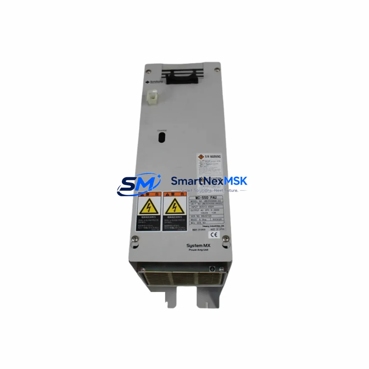
| Part Number | UMC554000-02 |
| Brand | PAU |
| Series | UMC Series |
| Product Type | AC Servo Drive |
| Origin | China (CN) |
| Compatibility | UMC Series servo systems; verify motor encoder type and bus protocol before installation |
| Application Environment | Industrial control cabinets, CNC systems, packaging lines, process automation |
| Installation | Panel-mount; follow OEM wiring diagram for power, encoder, and I/O terminals |
| Maintenance Recommendation | Inspect cooling fan, DC bus capacitors, and encoder cable shielding at each planned maintenance interval |
| Pre-Shipment Test | Power stage, encoder interface, communication bus, and I/O response verified |
| Warranty | 12 Months |
| Lead Time | In stock — ships within 1–3 business days |
Maintenance Planning for Continuous Operation
When a UMC554000-02 servo drive is flagged for replacement during a scheduled inspection or emergency fault response, experienced maintenance engineers know that the drive itself is rarely the only component that requires attention. A thorough site assessment should extend to the entire servo axis and its associated control cabinet infrastructure.
Begin by inspecting the servo motor paired with this drive — check encoder feedback cable integrity, connector seating, and motor winding insulation resistance. A degraded encoder cable is a frequent root cause of drive faults that are misdiagnosed as drive failures. Next, verify the 24VDC control power supply feeding the drive’s logic board; ripple voltage or undervoltage conditions can cause intermittent faults that survive a drive swap if the supply is not replaced concurrently.
Examine the regenerative braking resistor or braking unit if the axis handles high-inertia loads — an open-circuit braking resistor will trigger overvoltage faults on the replacement drive immediately after commissioning. Check the input line filter (EMC filter) and AC input fuses or circuit breaker upstream of the drive; a nuisance trip that caused the original failure may recur if the protection devices are not inspected.
On the signal side, inspect the I/O terminal block connections for the drive’s enable, fault reset, and speed reference inputs. Loose or corroded terminals on the terminal strip are a common source of intermittent enable faults. If the UMC system uses a fieldbus communication module (such as PROFIBUS-DP, CANopen, or EtherCAT adapter cards), verify the module’s firmware version is compatible with the replacement drive before going live.
For multi-axis systems, also inspect the shared DC bus connections and bus capacitor bank condition. In cabinets with multiple UMC drives, a failing capacitor bank can stress adjacent drives and shorten their service life. Finally, confirm that the PLC or motion controller axis parameters — including current limits, acceleration ramps, and encoder resolution settings — are correctly configured for the replacement unit before enabling the axis.
Site Replacement Workflow
Step 1 — Isolation: De-energize the cabinet following LOTO procedures. Discharge the DC bus and verify zero voltage before handling the drive.
Step 2 — Documentation: Photograph all wiring connections, terminal labels, and DIP switch or parameter settings on the outgoing drive before removal. Record the drive’s fault history from the HMI or PLC diagnostic log if accessible.
Step 3 — Removal: Disconnect power, motor, encoder, I/O, and communication cables in sequence. Remove the drive from the DIN rail or panel mount. Inspect the mounting bay for heat damage or contamination.
Step 4 — Installation: Mount the UMC554000-02 replacement unit. Reconnect all cables per the original wiring documentation. Verify encoder cable shielding is grounded at the drive end only to avoid ground loops.
Step 5 — Parameter Restore: Upload the saved parameter file from the PLC or HMI, or manually re-enter axis parameters. Confirm motor nameplate data, encoder type, and control mode match the application.
Step 6 — Commissioning: Perform a no-load jog test at low speed before enabling full-speed operation. Monitor DC bus voltage, output current, and encoder feedback on the drive’s diagnostic display or via the fieldbus during initial run-up.
Step 7 — Documentation Close-Out: Update the maintenance log with the replacement date, unit serial number, and any parameter changes. Tag the failed unit for failure analysis before disposal or return.
This workflow is designed to minimize axis downtime to under two hours for a prepared maintenance team with the spare unit on hand, compared to days or weeks waiting for emergency procurement.
Spare Parts Support FAQ
Q1: Is the UMC554000-02 a direct drop-in replacement for the original unit?
The UMC554000-02 is an original PAU UMC Series AC servo drive. In most UMC Series installations it is a direct replacement; however, we recommend verifying the motor encoder interface type (incremental vs. absolute), the communication bus protocol, and the firmware version compatibility with your system integrator or PAU documentation before installation to ensure full parameter compatibility.
Q2: What does the 12-month warranty cover?
The 12-month warranty covers manufacturing defects and functional failures under normal operating conditions from the date of shipment. Each unit is pre-tested before dispatch. Warranty claims are supported with a return and replacement process — contact sales@smartnexmsk.com with the unit serial number and fault description to initiate a claim.
Q3: How do you verify stock availability and lead time before placing an order?
In-stock units ship within 1–3 business days. For urgent requirements, contact us directly at +86 18259474341 or sales@smartnexmsk.com to confirm real-time availability and arrange expedited dispatch. We maintain buffer stock of high-demand UMC Series components to support emergency MRO requirements.
Q4: Can you supply other UMC Series components to complete our spare parts kit?
Yes. We supply a broad range of PAU UMC Series and compatible industrial automation components including servo motors, encoder cables, regenerative braking resistors, EMC line filters, communication adapter modules, and associated control cabinet hardware. Contact our technical sales team with your BOM or spare parts list for a consolidated quotation.
© 2026 SMARTNEXMSK. All rights reserved.
Original Source: https://smartnexmsk.com
Contact: sales@smartnexmsk.com | +86 18259474341