PORTER LB-366 NVL-003F Spare for LB-366 Automation: Spare Replacement & Industrial Downtime Risk Control
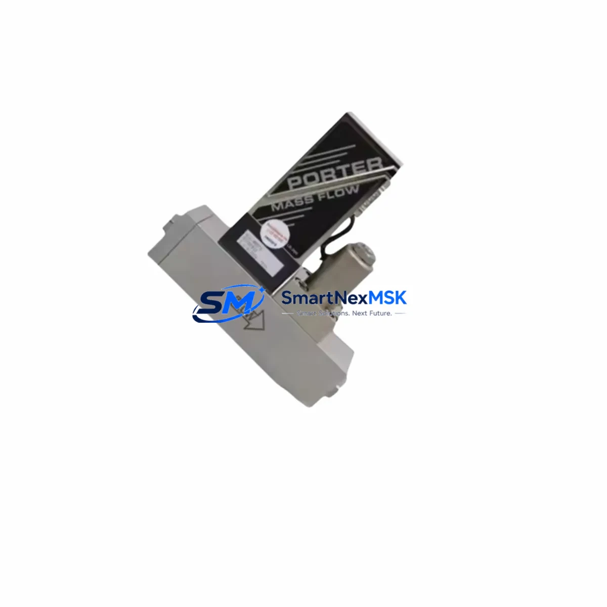
The PORTER LB-366 NVL-003F is an original thermal mass flow controller (MFC) designed for precision gas flow measurement and regulation in industrial process automation systems. As a maintenance-ready spare, the LB-366 NVL-003F is a critical component for facilities operating PORTER LB-366 Series flow control loops, where unplanned downtime caused by MFC failure can disrupt production, compromise process integrity, and trigger costly emergency procurement cycles.
Sourced directly from verified supply channels, each LB-366 NVL-003F unit is inspected and tested before shipment. Our 12-month warranty covers original defects and ensures your maintenance team receives a fully functional replacement that meets OEM specifications. Whether you are executing a planned turnaround, responding to an unscheduled fault, or building a strategic spare parts inventory for aging LB-366 Series installations, this unit ships ready for immediate site deployment.
Maintenance engineers and procurement specialists working with PORTER LB-366 Series systems recognize that MFC replacement is rarely an isolated task. A failing or drifted LB-366 NVL-003F typically signals the need for a broader inspection of the surrounding flow control circuit and control cabinet infrastructure. Proactive replacement of this unit should be accompanied by a systematic review of connected components to prevent repeat failures and ensure stable process resumption.
Spare Maintenance Table
| Parameter | Specification |
|---|---|
| Part Number / SKU | LB-366 NVL-003F |
| Brand | PORTER |
| Series | LB-366 |
| Product Type | Thermal Mass Flow Controller (MFC) |
| Measurement Principle | Thermal mass flow (capillary bypass) |
| Typical Flow Range | Per NVL-003F calibration range (contact for gas-specific data) |
| Control Signal | 0–5 VDC / 4–20 mA (standard PORTER LB-366 interface) |
| Power Supply | ±15 VDC (typical for LB-366 Series) |
| Process Connection | Compression fitting / VCR face seal (series-standard) |
| Compatible Systems | PORTER LB-366 Series flow panels, gas delivery systems, process automation cabinets |
| Application Environment | Semiconductor, chemical processing, laboratory gas control, industrial automation |
| Installation | Direct drop-in replacement for existing LB-366 NVL-003F installations |
| Maintenance Recommendation | Inspect valve seat, zero/span calibration, and upstream filter on replacement |
| Origin | USA (PORTER Instrument, Parker Hannifin Group) |
| Pre-shipment Testing | Yes — functional and leak test performed before dispatch |
| Warranty | 12 Months from date of shipment |
| Lead Time | In stock — ships within 1–3 business days |
Maintenance Planning for Continuous Operation
When replacing the PORTER LB-366 NVL-003F in a live process environment, experienced maintenance engineers treat the MFC swap as the starting point of a broader control loop audit — not the end point. The LB-366 NVL-003F sits at the intersection of gas supply, flow control, and process feedback, meaning its failure or degradation often reflects upstream or downstream stress on adjacent components.
Begin by inspecting the upstream gas filter or coalescing filter element installed before the MFC inlet. Particulate contamination is a leading cause of premature MFC valve wear and sensor drift in LB-366 Series installations. Replace the filter element if it has not been serviced within the last maintenance cycle.
Next, verify the ±15 VDC power supply module feeding the LB-366 NVL-003F. Voltage ripple or supply instability can cause erratic flow setpoint tracking and false zero readings. If the power supply is shared with other instruments in the control cabinet, check for load-induced voltage sag under full-system operation.
Inspect the signal wiring and terminal blocks connecting the MFC to the process controller or PLC analog output card. Corroded terminals, loose ferrules, or shielding breaks on the 0–5 VDC or 4–20 mA signal lines will introduce noise that mimics MFC malfunction. Clean and re-torque all signal terminals during the replacement procedure.
If the LB-366 NVL-003F is integrated into a PLC or DCS analog I/O module, verify the channel calibration and scaling after installation. An uncalibrated analog input channel will produce flow readings that appear correct at the MFC but are misrepresented at the controller level. This is a common source of post-replacement process deviation that is frequently misdiagnosed as a faulty spare.
For systems using a mass flow controller readout or ratio controller (such as a PORTER or compatible multi-channel readout box), confirm that the device address, gas factor, and full-scale range settings match the NVL-003F calibration data sheet shipped with the unit. Mismatched gas correction factors will produce systematic flow errors even with a perfectly functional MFC.
Review the solenoid valve or pneumatic shut-off valve installed downstream of the LB-366 NVL-003F. These valves are frequently overlooked during MFC replacement but are subject to seat wear and seal degradation that can cause backflow, pressure transients, or flow instability after the new MFC is commissioned. A leaking downstream valve will make a correctly installed LB-366 NVL-003F appear to drift or fail to hold setpoint.
Check the pressure regulator and inlet pressure to the MFC. The LB-366 NVL-003F is calibrated for a specific inlet-to-outlet differential pressure. If the upstream regulator has drifted or the supply pressure has changed since the original calibration, the MFC will not deliver accurate flow even after replacement. Confirm inlet pressure is within the OEM-specified range before commissioning the new unit.
Finally, if the LB-366 NVL-003F is part of a multi-channel gas panel or gas mixing manifold, inspect the manifold block fittings, check valves, and purge valve assemblies for leaks. A manifold leak will compromise the accuracy of all MFCs in the panel and can cause cross-contamination between gas lines — a safety and process quality concern that must be resolved before returning the system to service.
Site Replacement Workflow
Step 1 — Isolation and Purge: Close the upstream manual isolation valve and allow the gas line to depressurize fully. For hazardous or reactive gases, follow your site purge procedure using inert gas before disconnecting any fittings. Confirm zero pressure at the MFC inlet with a calibrated pressure gauge before proceeding.
Step 2 — Disconnection: Label and disconnect the signal cable connector from the LB-366 NVL-003F. Loosen the inlet and outlet process fittings carefully. For VCR face seal connections, inspect the gasket seat for damage before reassembly with the new unit. For compression fittings, use new ferrules on the replacement MFC.
Step 3 — Installation of LB-366 NVL-003F Spare: Mount the replacement unit in the same orientation as the original. Observe the flow direction arrow on the MFC body. Torque fittings to the manufacturer’s specification — over-tightening VCR fittings is a common installation error that damages the gasket seat and causes leaks. Reconnect the signal cable, ensuring correct pin orientation.
Step 4 — Leak Test: Before restoring gas flow, perform a leak test at the inlet and outlet fittings using an appropriate leak detection method for the process gas. Do not skip this step — a fitting leak on a newly installed MFC is far more common than a defective spare and will be misdiagnosed as a product fault.
Step 5 — Zero and Span Verification: With gas flow isolated, command the MFC to zero flow and verify the output reads 0% (0 VDC or 4 mA). Then command full-scale flow and verify the output tracks correctly. If the system uses a readout device, confirm the displayed flow matches the commanded setpoint within the specified accuracy band of the LB-366 NVL-003F.
Step 6 — Return to Service: Restore gas flow gradually. Monitor the process variable for the first 15–30 minutes of operation to confirm stable flow control. Document the replacement in your maintenance management system, including the serial number of the removed unit and the new spare, the date of replacement, and the post-installation verification results.
Spare Parts Support FAQ
Q1: Is the LB-366 NVL-003F a direct drop-in replacement for the original PORTER unit?
Yes. The LB-366 NVL-003F supplied by SMARTNEXMSK is an original PORTER spare that matches the OEM form, fit, and function of the installed unit. No mechanical modification or wiring change is required for a standard replacement. However, we recommend verifying the gas type, full-scale range, and calibration data on the unit label against your system documentation before installation, as PORTER LB-366 Series MFCs are available in multiple gas-specific calibrations.
Q2: What pre-shipment testing is performed on the LB-366 NVL-003F?
Each unit undergoes a functional power-on test and a leak integrity check before dispatch. Units that do not meet acceptance criteria are quarantined and not shipped. A test record is available upon request. The 12-month warranty covers defects in materials and workmanship from the date of shipment and applies to units installed and operated within OEM-specified conditions.
Q3: How should we manage LB-366 NVL-003F inventory for aging installations?
For facilities operating multiple LB-366 Series flow panels or gas delivery systems, we recommend maintaining a minimum of one LB-366 NVL-003F spare per critical gas line. MFCs in continuous service typically exhibit gradual sensor drift and valve wear after 5–8 years of operation. Proactive spare stocking eliminates emergency procurement lead times and allows planned replacement during scheduled maintenance windows rather than unscheduled shutdowns. Contact our team for volume pricing on multi-unit spare packages.
Q4: Can you supply LB-366 NVL-003F units calibrated for specific gases or flow ranges?
Yes. PORTER LB-366 Series MFCs are gas-specific instruments. If your application requires a calibration for a gas other than the standard NVL-003F configuration, or a different full-scale flow range, please provide your process gas type, desired full-scale range, and operating pressure conditions when placing your inquiry. We will confirm availability and lead time for your specific calibration requirement.
© 2026 SMARTNEXMSK. All rights reserved.
Original Source: https://smartnexmsk.com
Contact: sales@smartnexmsk.com | +86 18259474341