PROCESSELEKTRONIK PE1364B Retrofit-Ready DDCS-Modbus TCP Gateway: Seamless Compatibility for Legacy Control System Upgrades
The PROCESSELEKTRONIK PE1364B is a retrofit-ready protocol converter and gateway module engineered to bridge DDCS (Distributed Drive Control System) fieldbus networks with Modbus TCP/IP Ethernet infrastructure. Designed as a direct replacement for end-of-life and discontinued PE-series gateway modules, the PE1364B enables industrial facilities to modernize their drive communication architecture without replacing the entire control cabinet or reprogramming the host PLC from scratch.
For maintenance engineers and automation integrators managing aging PE-series drive systems, the PE1364B delivers a validated upgrade path that preserves existing program logic, minimizes rewiring, and reduces unplanned downtime. Whether you are migrating from an older DDCS ring topology to a TCP/IP backbone, expanding I/O capacity across distributed drive nodes, or recovering a failed gateway in a critical production line, the PE1364B provides the compatibility and reliability your retrofit project demands.
Upgrade Compatibility Table
| Parameter | Details |
|---|---|
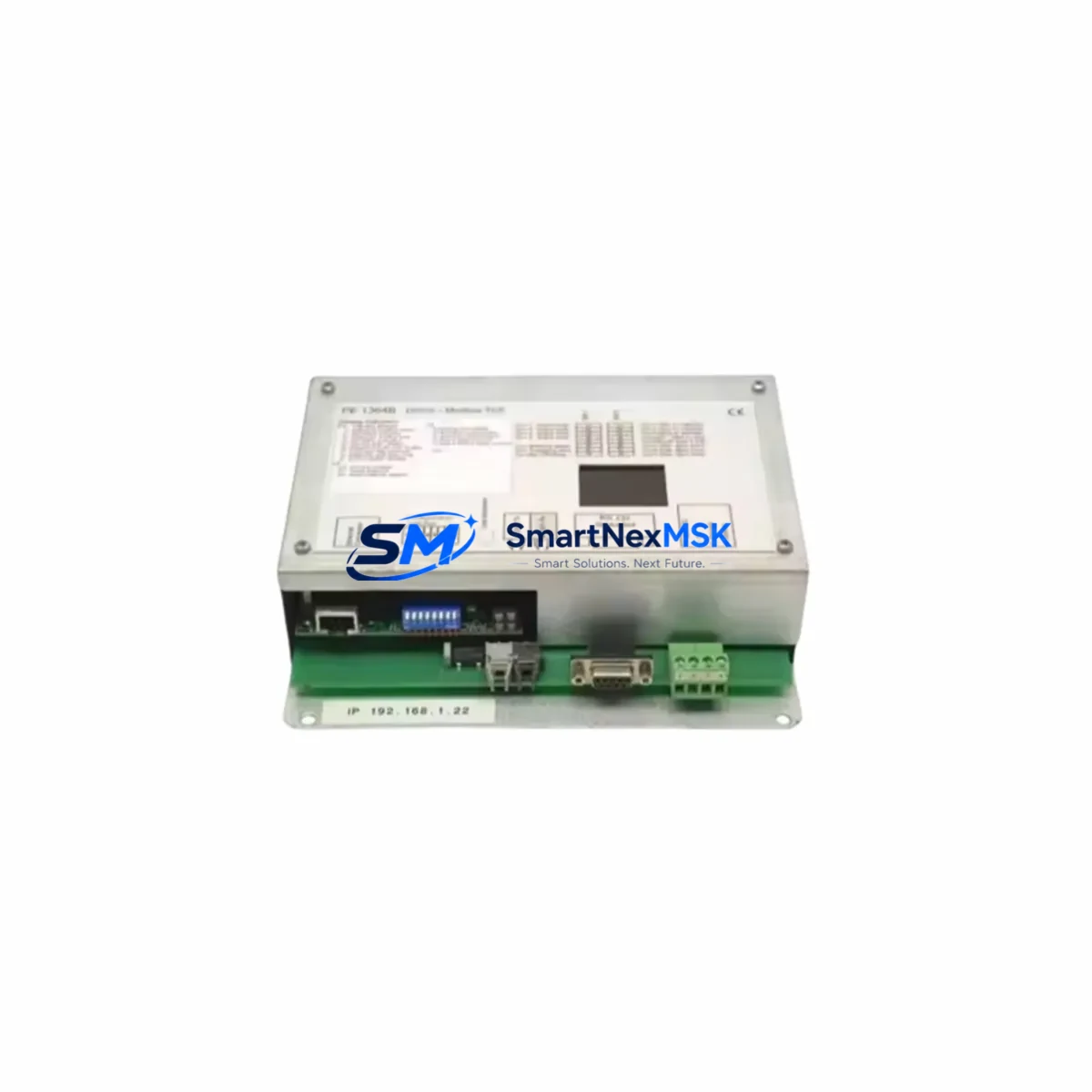
| SKU / Part Number | PE1364B |
| Brand / Manufacturer | PROCESSELEKTRONIK (Germany) |
| Function | DDCS to Modbus TCP Protocol Gateway |
| Compatible Series | PE-series drive systems; ABB ACS / DCS series with DDCS interface |
| Communication Interfaces | DDCS fiber-optic (CH0–CH3), RJ45 Ethernet (Modbus TCP) |
| Installation Type | DIN rail or panel mount; direct backplane replacement |
| Power Supply | 24 VDC (verify existing cabinet PSU capacity before installation) |
| Replacement Compatibility | Drop-in for discontinued PE1364, PE1364A variants |
| Protocol Migration | DDCS → Modbus TCP/IP; supports legacy register mapping |
| Commissioning Requirement | Node address configuration; Modbus register table verification |
| Warranty | 12 Months — covers manufacturing defects and functional failure |
| Pre-shipment Testing | Full functional test performed before dispatch |
Retrofit Planning for Existing Automation Systems
A successful PE1364B retrofit begins with a thorough audit of the existing control cabinet. Before removing the legacy gateway, engineers should document the DDCS node addresses assigned to each drive — typically configured via DIP switches or parameter settings on the drive’s RDCO or RDNA adapter board. These addresses must be replicated exactly on the PE1364B to avoid communication conflicts with the host controller.
Power supply capacity is a critical checkpoint. The PE1364B draws 24 VDC from the cabinet’s auxiliary power rail. If the existing PSU — such as a SITOP or Phoenix Contact QUINT series unit — is already operating near its rated output, adding the gateway module may require either a PSU upgrade or load redistribution across the rail. Always measure actual rail voltage under load before commissioning.
Terminal wiring for the Modbus TCP side connects via standard RJ45 patch cable to the plant’s Ethernet switch. If the existing network uses managed switches with VLAN segmentation, confirm that the PE1364B’s IP address falls within the correct subnet and that Modbus TCP port 502 is not blocked by firewall rules. For the DDCS fiber side, use the correct ST-type fiber connectors and verify that the optical power budget is within specification — degraded fiber links are a common cause of intermittent DDCS communication faults.
When the PE1364B replaces a failed gateway in a running system, the Modbus register map used by the SCADA or DCS host — such as a Siemens S7-300, S7-400, or an ABB AC500 controller — must be preserved. Export the existing register configuration from the host PLC’s communication function block before swapping the module. After installation, reload the register map and perform a live comparison of drive status words and control words to confirm data integrity.
HMI screens connected to the drive system — whether a Siemens TP700 Comfort, a Weintek MT8000 series panel, or a standalone SCADA workstation — should be tested against the PE1364B’s Modbus TCP responses before returning the line to production. Pay particular attention to drive fault code registers, speed reference scaling, and run/stop command bits, as these are the most common sources of post-retrofit discrepancies.
For systems that include additional I/O expansion modules, communication modules, or remote I/O racks connected via Profibus DP or DeviceNet alongside the DDCS ring, the PE1364B’s installation should not affect those parallel communication paths. However, if the legacy gateway also served as a Profibus master or DeviceNet scanner, a separate replacement module will be required for that protocol segment. In such cases, a staged migration — replacing the DDCS gateway first, then addressing the secondary fieldbus — is strongly recommended to isolate variables during commissioning.
Backplane and rack compatibility should be verified if the PE1364B is installed in a modular rack system. Confirm that the rack’s backplane connector pinout matches the PE1364B’s edge connector specification. For standalone DIN rail installations, ensure adequate clearance for fiber cable routing and Ethernet patch cable bend radius.
Downtime Control During System Migration
Minimizing production downtime during a PE1364B gateway replacement requires careful pre-staging. Before the maintenance window opens, prepare the replacement module with its IP address, subnet mask, and gateway pre-configured using the PE1364B’s web interface or configuration software. Load the Modbus register table from the backup taken during the audit phase so that the module is ready to communicate the moment it is powered on.
During the swap, follow a structured sequence: isolate the drive system from the host PLC’s control outputs (switch to local control mode on each drive), remove the failed gateway, install the PE1364B, restore fiber connections, restore Ethernet, and power up. Verify DDCS link status LEDs on the PE1364B before releasing drives back to remote control. This sequence prevents uncontrolled drive starts during the transition and protects both personnel and equipment.
Original program logic in the host PLC does not need to be modified if the Modbus register map is preserved. The PE1364B is designed to maintain register address compatibility with its predecessors, meaning that function blocks, structured text routines, and ladder logic referencing drive data blocks will continue to operate without modification. This is a critical advantage in facilities where PLC program changes require formal change management approval and extended validation cycles.
For systems where a hot-swap is not feasible, schedule the migration during a planned maintenance shutdown and use the opportunity to also inspect and replace aging fiber patch cables, verify terminal torque on the 24 VDC power connections, and update drive firmware if required. Combining these tasks within a single downtime window maximizes the return on the maintenance investment.
Retrofit Support FAQ
Q1: Is the PE1364B a direct drop-in replacement for the PE1364 and PE1364A?
Yes. The PE1364B maintains backward compatibility with the PE1364 and PE1364A in terms of DDCS node addressing, Modbus register structure, and physical mounting. Minor firmware differences may require a one-time parameter verification during commissioning, but no hardware modifications to the cabinet are required.
Q2: What pre-shipment testing is performed on the PE1364B?
Each PE1364B unit undergoes a full functional test prior to dispatch, including DDCS communication loop verification, Modbus TCP register read/write validation, and power supply input range testing. A test report is available upon request. All units are covered by a 12-month warranty against manufacturing defects and functional failure from the date of shipment.
Q3: How do I verify wiring and terminal compatibility before installation?
Download the PE1364B installation manual and compare the terminal block layout against your existing cabinet drawings. Pay particular attention to the 24 VDC input polarity, the DDCS fiber channel assignments (CH0 transmit/receive orientation), and the Ethernet port location. If your cabinet uses a different terminal pitch or requires a specific cable entry direction, contact our technical team before installation.
Q4: Can the PE1364B be used in systems with mixed communication protocols, such as Profibus DP and Modbus TCP running simultaneously?
The PE1364B handles the DDCS-to-Modbus TCP conversion exclusively. If your system also requires Profibus DP, DeviceNet, or other fieldbus segments, those protocols must be managed by separate gateway or communication modules installed in parallel. Our team can advise on compatible modules for multi-protocol retrofit projects.
© 2026 SMARTNEXMSK. All rights reserved.
Original Source: https://smartnexmsk.com
Contact: sales@smartnexmsk.com | +86 18259474341