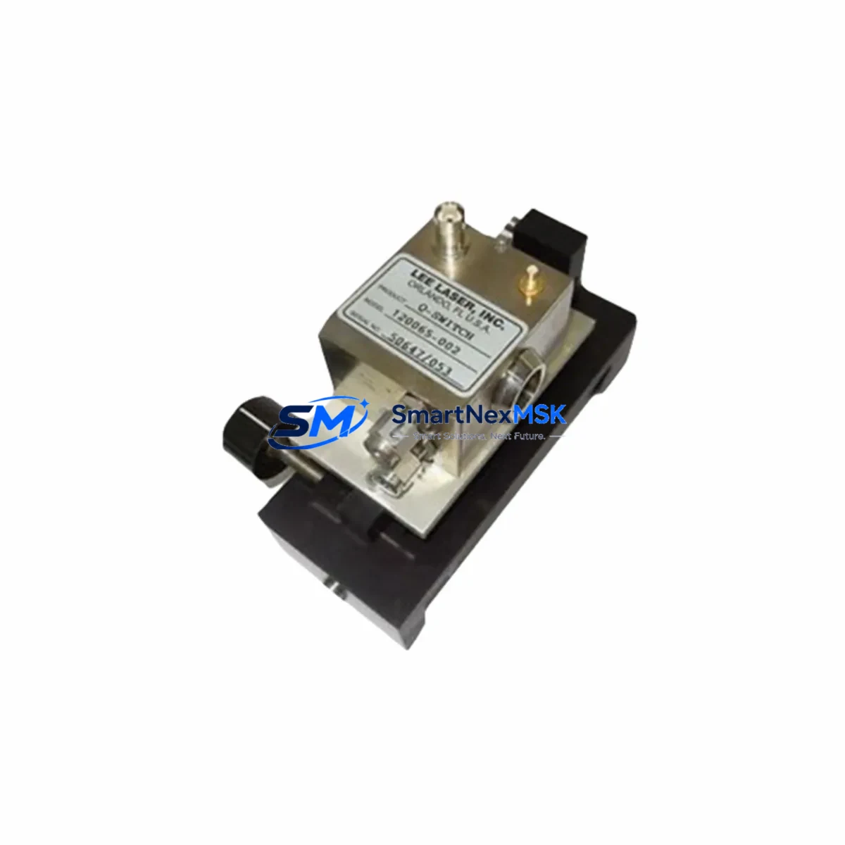
Q-SWITCH 120065-002 Spare for 120065 Series Automation: Precision Spare Parts for Industrial Downtime Control
The Q-SWITCH 120065-002 is an original-grade switch module designed for deployment within the 120065 Series industrial automation architecture. As a maintenance-ready spare, it is engineered to support rapid field replacement, minimize unplanned downtime, and sustain continuous operation across demanding manufacturing, process control, and infrastructure environments. Whether you are managing a scheduled overhaul, responding to an emergency fault, or building a proactive spare parts inventory, the 120065-002 delivers the electrical reliability and dimensional compatibility required for seamless integration into existing control cabinet configurations.
Maintenance engineers and procurement specialists working with Q-SWITCH automation systems recognize the 120065-002 as a critical line-replaceable unit (LRU). Its role spans daily inspection routines, fault isolation procedures, and long-term system life extension programs — particularly in aging installations where original components are no longer available through standard distribution channels. Sourcing a verified spare in advance is the most effective strategy for protecting production continuity and avoiding costly emergency procurement delays.
Spare Maintenance Table
| Parameter | Specification |
|---|---|
| Part Number / SKU | 120065-002 |
| Brand | Q-SWITCH |
| Series | 120065 Series |
| Product Type | Switch Module |
| Origin | China (CN) |
| Compatibility | Q-SWITCH 120065 Series automation systems; cross-compatible with equivalent switch module slots in same-generation control cabinets |
| Mounting / Installation | DIN rail or panel-mount per 120065 Series mechanical specification; refer to OEM installation guide for torque and clearance requirements |
| Operating Environment | Industrial automation environments; suitable for control cabinet installation with standard ventilation and EMC shielding |
| Electrical Interface | Compatible with 120065 Series wiring harness and terminal block assignments |
| Maintenance Recommendation | Inspect contact surfaces and wiring connections during scheduled PM cycles; replace if contact resistance exceeds OEM threshold or switching response degrades |
| Warranty | 12 Months from date of shipment |
| Pre-shipment Testing | Functional verification performed prior to dispatch |
| Lead Time | In-stock; same-day or next-business-day dispatch available |
Maintenance Planning for Continuous Operation
Effective maintenance planning for a Q-SWITCH 120065 Series control system extends well beyond the switch module itself. When a 120065-002 replacement is scheduled or triggered by a fault condition, experienced maintenance engineers use the event as an opportunity to inspect the broader electrical environment within the same control cabinet. This approach reduces repeat call-outs and extends the mean time between failures (MTBF) for the entire system.
During a 120065-002 replacement, the following associated components should be inspected or staged as co-spares:
- Power supply module — Verify output voltage stability and ripple within the 120065 Series power rail. A degraded power supply is a common root cause of switch module premature failure.
- I/O expansion modules — Check adjacent digital input and output cards for contact wear, blown fuses, or communication errors that may have contributed to the switching fault.
- Terminal blocks and wiring harnesses — Inspect screw-clamp or spring-cage terminals connected to the 120065-002 for oxidation, loose conductors, or insulation breakdown, particularly in high-vibration or high-humidity environments.
- Relay output modules — If the switch module interfaces with relay-driven loads, inspect coil resistance and contact condition on associated relay modules within the same cabinet section.
- Communication interface module — Verify that the fieldbus or serial communication card (e.g., PROFIBUS, Modbus RTU, or Ethernet/IP adapter) serving the 120065 Series rack is operating without CRC errors or timeout faults.
- Signal isolators — For analog signal paths passing through the same cabinet, confirm that signal isolation barriers are within calibration and free of ground loop interference.
- Fuse holders and protection devices — Replace any blown or discolored fuses in the 120065 Series power distribution section and verify that circuit breakers are within rated trip tolerance.
- HMI panel or operator interface — If the 120065-002 fault was operator-reported via an HMI alarm, confirm that the HMI communication link to the controller is stable and that alarm history has been reviewed for precursor events.
- Backplane or rack assembly — Inspect the module backplane for bent connector pins, corrosion, or mechanical damage that could cause intermittent contact with the replacement 120065-002.
- Surge protection devices (SPDs) — Verify that transient voltage suppressors on the input power rail and field wiring circuits are intact, as switching module failures are frequently associated with upstream surge events.
Maintaining a minimum of one 120065-002 unit in your on-site spare parts inventory — alongside the associated power and I/O modules listed above — is the recommended strategy for facilities operating Q-SWITCH 120065 Series systems in critical production roles. Procurement engineers should establish a replenishment trigger at the point of first use to ensure continuous stock availability without over-investment in slow-moving inventory.
Site Replacement Workflow
Replacing the Q-SWITCH 120065-002 in the field is a structured process designed to minimize system downtime and ensure full restoration of switching function without configuration loss or compatibility issues.
Step 1 — Fault Confirmation: Use the system controller’s diagnostic interface or HMI alarm log to confirm that the 120065-002 is the source of the fault. Distinguish between a hard module failure and a wiring or load-side fault before proceeding with replacement.
Step 2 — Safe Isolation: De-energize the relevant circuit section following your site’s lockout/tagout (LOTO) procedure. Confirm zero-energy state with a calibrated voltage tester before opening the control cabinet.
Step 3 — Module Removal: Disconnect field wiring from the terminal block associated with the 120065-002. Document terminal assignments with a photograph or wiring diagram reference before disconnection. Remove the module from its mounting position per the 120065 Series mechanical guide.
Step 4 — Compatibility Verification: Confirm that the replacement 120065-002 unit matches the part number, revision level, and firmware version (if applicable) of the removed module. Cross-reference with the system’s bill of materials or spare parts register.
Step 5 — Installation and Wiring: Install the replacement module, reconnect field wiring to the documented terminal assignments, and verify torque on all screw-clamp connections. Restore power to the circuit section.
Step 6 — Functional Test: Execute a switching function test from the controller or HMI to confirm that the 120065-002 is responding correctly to command signals. Clear any latched fault codes and verify that the system returns to normal operating state.
Step 7 — Documentation: Record the replacement in the site maintenance log, including the date, technician name, fault description, and new module serial number. Update the spare parts inventory register to trigger replenishment.
This workflow is applicable to both planned maintenance replacements and emergency fault recovery scenarios. The structured approach ensures that the replacement 120065-002 is installed correctly the first time, reducing the risk of repeat failures caused by installation error or overlooked wiring faults.
Spare Parts Support FAQ
Q1: What is the shelf life and storage recommendation for the Q-SWITCH 120065-002 spare module?
The 120065-002 should be stored in its original anti-static packaging in a dry, temperature-controlled environment (typically 0–40°C, <85% RH non-condensing). Under these conditions, the module can be stored for up to 3–5 years without degradation of electrical performance. Inspect the module for physical damage and verify packaging integrity before installation if stored for extended periods.
Q2: How do I verify compatibility before installing the 120065-002 in my existing Q-SWITCH system?
Compatibility verification should include: (1) confirming the part number matches the module position in your system’s BOM or spare parts register; (2) checking that the revision or hardware version is consistent with the installed base; and (3) verifying that the wiring terminal assignments match your documented field wiring. If your system has been modified from its original configuration, consult the as-built wiring diagrams before installation.
Q3: What pre-shipment testing is performed on the 120065-002 before dispatch?
Each 120065-002 unit undergoes functional verification prior to shipment, including switching response testing and basic electrical continuity checks. Units are dispatched in anti-static packaging with a test-passed label. A 12-month warranty from the date of shipment covers manufacturing defects and functional failures under normal operating conditions. Warranty claims are supported by our technical team with replacement or repair options.
Q4: Can the 120065-002 be used as a long-term replacement for discontinued or obsolete Q-SWITCH switch modules in the same series?
Yes. The 120065-002 is sourced to support legacy system life extension programs where original OEM supply has been discontinued. It is suitable as a direct replacement for equivalent switch module positions within the 120065 Series architecture. For systems where the original module revision is no longer available, our technical support team can assist with compatibility assessment and alternative sourcing options to minimize the risk of system modification.
© 2026 SMARTNEXMSK. All rights reserved.
Original Source: https://smartnexmsk.com
Contact: sales@smartnexmsk.com | +86 18259474341