Reflexite AU350 Maintenance-Ready Spare AU Series Automation
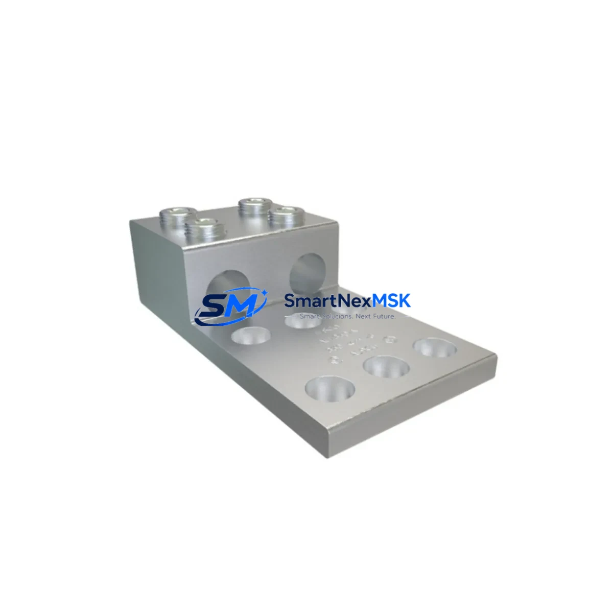
The Reflexite AU350 is an original compression terminal lug engineered for heavy-duty conductor termination in AU Series industrial automation and control systems. For maintenance engineers managing aging control cabinets or executing planned shutdowns, the AU350 represents a critical interface component — one whose failure can cascade into unplanned downtime across an entire production line. Sourced directly from verified supply channels, each AU350 unit is inspected and tested prior to shipment, ensuring drop-in compatibility with existing AU Series wiring harnesses and terminal blocks.
In industrial environments where uptime is measured in production yield, having a verified spare on the shelf is not optional — it is a maintenance discipline. The AU350 compression terminal lug is commonly found in motor control centers (MCCs), PLC power distribution panels, DCS marshalling cabinets, and field junction boxes. Its robust copper compression design ensures low-resistance, vibration-resistant connections that meet the demands of continuous industrial operation.
Maintenance and procurement engineers sourcing the AU350 should simultaneously audit adjacent components in the same electrical circuit. When replacing a compression terminal lug of this class, it is standard practice to inspect the associated cable ferrules, busbar connectors, and insulated end caps for signs of thermal stress or oxidation. If the AU350 is installed in a PLC power supply rail, the 24VDC or 48VDC power supply module feeding that rail should be load-tested. Nearby DIN rail terminal blocks — particularly feed-through and disconnect types — should be torque-checked to manufacturer specification.
In control cabinet environments, the AU350 often works alongside components such as miniature circuit breakers (MCBs), residual current devices (RCDs), and surge protection devices (SPDs) on the same distribution bar. A comprehensive cabinet inspection during AU350 replacement should include verification of the grounding bus bar continuity, PE conductor integrity, and the condition of cable duct covers and cable ties. For systems with I/O modules connected downstream, signal integrity should be confirmed after re-termination — particularly for analog 4–20 mA loops where contact resistance directly affects measurement accuracy.
For facilities running legacy automation systems where the AU Series hardware is no longer in active production, the AU350 spare part becomes a long-term asset. Procurement teams are advised to maintain a minimum buffer stock of 3–5 units per active panel, particularly in high-vibration or high-humidity environments where terminal degradation accelerates. Pairing the AU350 with compatible heat-shrink insulation sleeves and cable end markers ensures that replacement work is completed to documentation standards without requiring re-labeling of the entire loom.
SMARTNEXMSK maintains long-term supply continuity for the Reflexite AU350 and related AU Series components. All units are shipped with test documentation and are covered by a 12-month warranty against manufacturing defects. Expedited shipping is available for emergency breakdown scenarios.
Spare Maintenance Table
| Parameter | Specification |
|---|---|
| Part Number | AU350 |
| Brand | Reflexite |
| Series | AU Series |
| Product Type | Compression Terminal Lug |
| Conductor Cross-Section | Up to 350 mm² (inferred from SKU designation) |
| Connection Method | Compression / Crimp |
| Material | Electrolytic Copper, Tin-Plated |
| Country of Origin | Germany |
| Compatibility | AU Series automation panels, MCC, DCS marshalling cabinets |
| Installation Environment | Industrial control cabinets, field junction boxes, motor control centers |
| Maintenance Interval | Inspect every 12 months or per planned shutdown schedule |
| Warranty | 12 Months — manufacturing defects covered |
| Pre-Shipment Testing | Yes — electrical continuity and dimensional inspection |
Maintenance Planning for Continuous Operation
A structured maintenance plan for systems using the Reflexite AU350 should account for the full electrical path from the upstream power source to the downstream load. During scheduled cabinet inspections, engineers should verify the condition of the following components in the same circuit or enclosure:
The 24VDC power supply module feeding the PLC or I/O rack should be load-tested and its output voltage confirmed within ±1% tolerance. DIN rail-mounted terminal blocks — including feed-through, fused, and disconnect variants — should be inspected for discoloration, loose screws, and conductor pull-out resistance. Miniature circuit breakers (MCBs) protecting individual circuits should be trip-tested annually. Cable ferrules and end sleeves on all conductors terminating at the AU350 lug should be checked for deformation or corrosion.
In systems with analog I/O modules, re-termination of the AU350 must be followed by a loop calibration check to confirm 4–20 mA signal integrity. Surge protection devices (SPDs) on the same busbar should have their status indicators verified. Grounding bus bars and PE conductors must be continuity-tested after any terminal work. For panels with communication modules (PROFIBUS, PROFINET, or Modbus RTU), cable shielding termination at the cabinet entry point should be inspected simultaneously. Relay output modules and contactor coil terminals in the same cabinet should be torque-verified to prevent intermittent contact faults. Finally, cable duct fill levels and cable tie integrity should be assessed to ensure no mechanical stress is placed on newly terminated conductors.
Site Replacement Workflow
Step 1 — Isolation: De-energize the circuit at the upstream MCB or isolator. Verify absence of voltage with a calibrated multimeter at the AU350 lug termination point.
Step 2 — Documentation: Photograph the existing termination, cable routing, and conductor labeling before removal. Cross-reference with the panel wiring diagram (P&ID or E-plan schematic).
Step 3 — Removal: Using the correct compression tool die set for the AU350 lug size, cut the old lug cleanly. Strip the conductor to the correct insertion depth per the AU350 datasheet.
Step 4 — Installation: Insert the conductor fully into the AU350 barrel. Apply the correct compression die and crimp to the manufacturer’s specified force. Inspect the crimp for barrel deformation and conductor exposure.
Step 5 — Verification: Perform a continuity test and insulation resistance (IR) test at 500V DC before re-energizing. Confirm torque on all adjacent terminal connections.
Step 6 — Re-energization and Functional Test: Restore power and confirm correct system operation. Log the replacement in the maintenance management system (CMMS) with date, technician ID, and part number AU350.
This workflow minimizes downtime, maintains system compatibility, and ensures the replacement meets the same electrical performance as the original Reflexite AU350.
Spare Parts Support FAQ
Q1: Is the AU350 a direct replacement for the original Reflexite component, or will modifications be required?
The AU350 is supplied as an original Reflexite compression terminal lug. It is dimensionally and electrically equivalent to the factory-installed component in AU Series panels. No modifications to the cable or panel are required for a standard replacement, provided the conductor cross-section matches the lug specification.
Q2: What is the recommended inventory strategy for the AU350 in a multi-panel facility?
For facilities operating three or more AU Series panels, a minimum buffer of 5 units per site is recommended. High-vibration or high-humidity environments may require higher buffer levels. SMARTNEXMSK supports blanket purchase orders and scheduled replenishment to maintain your spare parts inventory without capital overcommitment.
Q3: How is the AU350 tested before shipment?
Each AU350 unit undergoes electrical continuity verification and dimensional inspection prior to dispatch. Units are packaged individually to prevent transit damage. A test report is available upon request for quality-critical applications.
Q4: What warranty coverage applies to the AU350, and what does it include?
All AU350 units supplied by SMARTNEXMSK carry a 12-month warranty from the date of shipment. The warranty covers manufacturing defects including material failure, dimensional non-conformance, and electrical continuity faults. Field installation damage or misapplication is excluded. Warranty claims are processed within 5 business days with replacement or credit options.
© 2026 SMARTNEXMSK. All rights reserved.
Original Source: https://smartnexmsk.com
Contact: sales@smartnexmsk.com | +86 18259474341