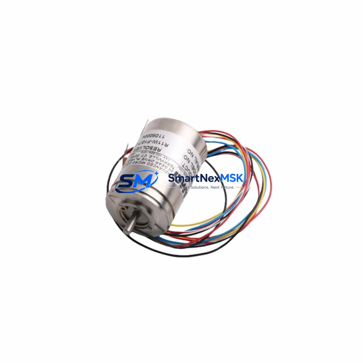
RESOLVER R11W-F10/7-2 Retrofit-Ready Rotary Transformer for R11W Series Control Systems
The RESOLVER R11W-F10/7-2 is a precision rotary transformer engineered for seamless integration into legacy R11W Series servo drive and motion control systems. As industrial facilities face increasing pressure to modernize aging automation infrastructure without full system overhauls, the R11W-F10/7-2 provides a validated, drop-in retrofit solution that preserves existing wiring topology, encoder feedback loops, and drive parameter configurations. Whether you are replacing a failed unit on a production line or executing a planned upgrade of an end-of-life servo axis, this resolver delivers the electrical and mechanical compatibility required to restore full system functionality with minimal downtime.
Sourced directly from verified supply channels and subjected to outgoing electrical testing prior to shipment, each R11W-F10/7-2 unit is backed by a 12-month warranty covering manufacturing defects and performance deviations. Stock is maintained to support urgent replacement orders, with same-day dispatch available for confirmed in-stock quantities.
Upgrade Compatibility Table
| Parameter | R11W-F10/7-2 Specification | Retrofit Notes |
|---|---|---|
| Series Compatibility | R11W Series | Direct replacement for R11W-series servo axes |
| Resolver Type | Rotary Transformer (brushless) | No brush maintenance required post-installation |
| Electrical Interface | Standard resolver signal (sin/cos, reference winding) | Verify drive resolver input card pinout before wiring |
| Mechanical Mounting | Flange-mount, shaft coupling per R11W spec | Confirm shaft diameter and coupling type on existing motor |
| Communication Compatibility | Analog resolver signal (RDC-compatible) | Compatible with resolver-to-digital converter (RDC) cards in legacy drives |
| Replacement Recommendation | Direct OEM-equivalent replacement | No drive parameter re-scaling required in most R11W applications |
| Commissioning Focus | Phase alignment, offset calibration | Re-run resolver offset auto-tune after installation |
| Warranty | 12 Months | Covers electrical performance and mechanical integrity |
Retrofit Planning for Existing Automation Systems
Successful integration of the R11W-F10/7-2 into an existing control architecture requires a structured pre-installation review. Begin by auditing the servo drive cabinet to confirm the resolver feedback card type — common configurations in R11W-based systems include dedicated resolver input modules mounted on the drive’s expansion backplane. Verify that the resolver cable harness, typically a shielded twisted-pair assembly routed from the motor terminal box to the drive cabinet, is intact and free of insulation damage before reusing it with the replacement unit.
On the power supply side, confirm that the 24 VDC control power rail supplying the drive’s logic section and the resolver excitation circuit is within tolerance. Voltage sag on this rail — often caused by aging power supply modules or overloaded distribution terminals — can produce erratic resolver feedback signals that mimic a faulty resolver. In many R11W retrofit projects, replacing the resolver in isolation resolves the fault only after the control power supply module is also serviced or replaced.
For systems where the R11W servo axis is coordinated with a PLC — such as a Siemens S7-300 or S7-400 CPU communicating over PROFIBUS-DP — verify that the axis position data block in the PLC program references the correct drive node address. After swapping the resolver, the drive may require a re-initialization sequence before the PLC’s motion function block (e.g., MC_Home or equivalent) can re-establish the axis reference position. Coordinate this step with the HMI operator panel update if the axis position is displayed on a WinCC or similar SCADA screen.
In multi-axis cabinets, the R11W-F10/7-2 is frequently installed alongside companion components such as servo drive power modules, DC bus capacitor banks, and braking resistor assemblies. If the retrofit scope extends to adjacent axes, consider simultaneously inspecting the shared DC bus connections and the inter-axis communication cables. Systems using DRIVE-CLiQ or similar digital encoder interfaces on newer axes may require a gateway or protocol converter if the R11W resolver axis is being integrated into a mixed-feedback architecture.
I/O expansion modules connected to the same control rack — including digital input/output modules handling axis enable signals, limit switch inputs, and fault relay outputs — should be verified for correct terminal mapping after the resolver swap. Incorrect wiring of the axis enable interlock can prevent the drive from accepting the new resolver signal even after a successful hardware installation. Always cross-reference the terminal strip wiring diagram against the as-built cabinet documentation before powering up.
Programming cable access to the drive (via RS-232, USB, or Ethernet service port depending on drive generation) is essential for reading fault codes, running the resolver offset calibration routine, and confirming that the feedback signal quality indicators are within acceptable limits. Retain a backup copy of the drive parameter set before beginning the retrofit — this allows rapid restoration if the commissioning process reveals an incompatibility requiring parameter adjustment.
Downtime Control During System Migration
Minimizing production downtime during a resolver replacement on an active manufacturing line requires advance preparation and a disciplined commissioning sequence. Before the maintenance window opens, pre-configure a spare drive with the backed-up parameter set from the affected axis. This allows a parallel swap strategy: if the resolver replacement alone does not clear the fault within the allocated window, the pre-configured spare drive can be substituted immediately without re-entering parameters manually.
Preserve the original PLC program logic by exporting a timestamped backup to an offline programming station before any hardware changes are made. For axes controlled by motion function blocks, document the current homing mode, software travel limits, and velocity/acceleration profiles. These values must be re-entered or verified after the resolver calibration is complete, as some drive firmware versions reset motion parameters to defaults during a resolver re-initialization sequence.
To maintain field control continuity during the swap, coordinate with the control room to place the affected axis in a safe, parked position before de-energizing the drive. If the axis is part of a synchronized multi-axis group, inhibit the group coordinator in the PLC to prevent other axes from attempting to follow a position reference from the offline axis. Re-enable the group only after the replacement resolver has passed the offset calibration check and the drive has confirmed a clean feedback signal.
Post-installation, conduct a low-speed jog test across the full travel range of the axis before returning it to automatic mode. Monitor the resolver signal quality diagnostic in the drive’s commissioning software during the jog to confirm that signal amplitude and phase are consistent across the entire mechanical range. Document the final resolver offset value and update the maintenance record before closing the work order.
Retrofit Support FAQ
Q: Is the R11W-F10/7-2 a direct drop-in replacement for the original resolver on R11W series servo motors?
A: Yes. The R11W-F10/7-2 is dimensionally and electrically equivalent to the original resolver specification for R11W series applications. In most installations, no mechanical modification or drive parameter re-scaling is required. A resolver offset auto-tune should be performed after installation to confirm phase alignment.
Q: What wiring checks are required before installing the replacement resolver?
A: Inspect the resolver cable for continuity and insulation integrity on all signal conductors (excitation reference, sin, cos, and shield). Verify that the cable shield is grounded at the drive end only, per the original wiring specification. Confirm terminal tightness at both the motor junction box and the drive resolver input card before applying power.
Q: How is compatibility with the existing drive and PLC program verified after installation?
A: After completing the resolver offset calibration in the drive commissioning tool, perform a low-speed jog test and confirm that the position feedback value in the PLC data block increments correctly and without noise spikes. If the axis uses a homing routine, execute a full home cycle and verify that the home position matches the pre-retrofit reference. Check the HMI display for correct axis position readback before returning the axis to automatic production mode.
Q: What does the 12-month warranty cover, and what is the outgoing test procedure?
A: Each R11W-F10/7-2 unit undergoes electrical performance testing prior to shipment, including excitation winding resistance, signal winding output amplitude, and insulation resistance checks. The 12-month warranty covers defects in materials and workmanship, including electrical performance deviations from specification. Units that develop a fault within the warranty period are eligible for replacement or repair subject to inspection. Contact sales@smartnexmsk.com with your order reference and fault description to initiate a warranty claim.
© 2026 SMARTNEXMSK. All rights reserved.
Original Source: https://smartnexmsk.com
Contact: sales@smartnexmsk.com | +86 18259474341