Reveal Imaging 10023-27 Retrofit-Ready FPGA Adapter for Vision Systems
The Reveal Imaging 10023-27 FPGA Adapter Board is a precision interface module engineered for machine vision and industrial imaging platforms. As legacy vision systems age and original components reach end-of-life, the 10023-27 provides a verified, drop-in retrofit path that preserves existing frame grabber architecture, camera link configurations, and image processing pipelines without requiring full system redesign. For maintenance engineers managing aging inspection lines and procurement teams sourcing discontinued imaging components, this adapter board represents a reliable, cost-effective alternative to full platform replacement.
In industrial environments — from automotive body inspection and semiconductor wafer handling to pharmaceutical blister pack verification and food sorting lines — machine vision systems are deeply integrated into production logic. Replacing a failed or obsolete FPGA adapter board without disrupting upstream PLC triggers, downstream reject signals, or HMI display logic demands a component that is electrically and functionally compatible with the original installation. The 10023-27 is sourced, tested, and shipped to meet exactly these requirements.
Upgrade Compatibility Table
| Parameter | Details |
|---|---|
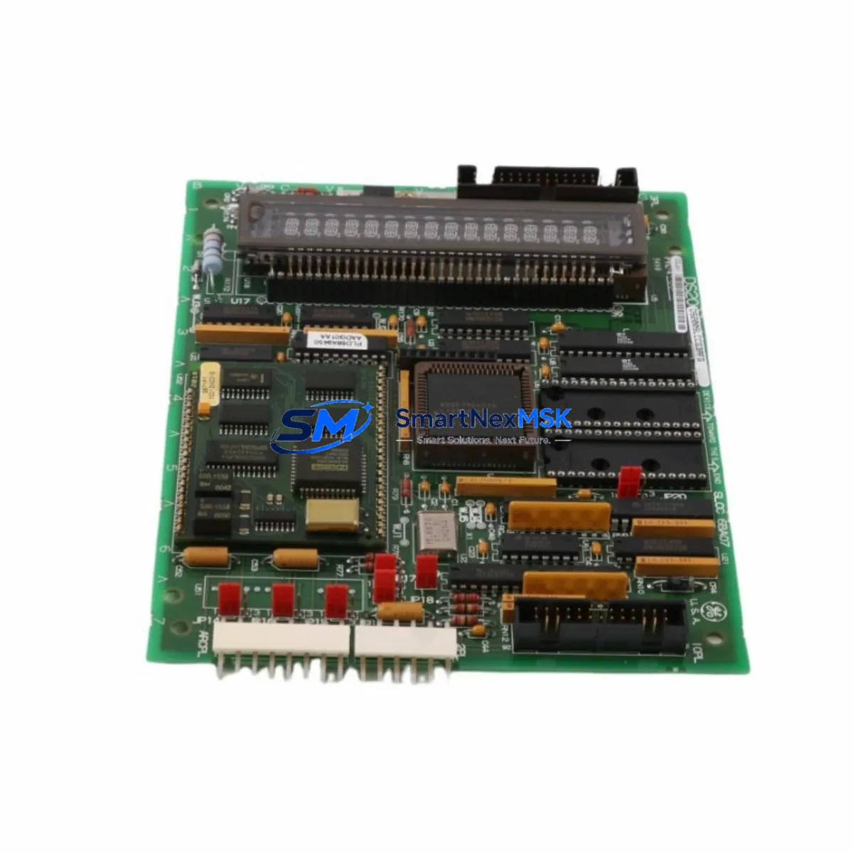
| SKU | 10023-27 |
| Brand | Reveal Imaging |
| Product Type | FPGA Adapter Board |
| Application | Machine Vision / Industrial Imaging Interface |
| Interface Compatibility | Camera Link, frame grabber backplane interface |
| Installation | Board-level replacement; matches original mounting footprint |
| Communication Compatibility | Compatible with existing vision controller communication protocols |
| Replacement Recommendation | Direct retrofit for legacy Reveal Imaging vision platforms |
| Commissioning Notes | Verify FPGA firmware version, camera link cable routing, and trigger I/O mapping prior to power-up |
| Origin | USA |
| Weight | 1,850 g (packaged) |
| Warranty | 12-Month Warranty — tested before shipment |
Retrofit Planning for Existing Automation Systems
A successful retrofit of the Reveal Imaging 10023-27 begins well before the board is physically installed. Engineers should start by auditing the full vision enclosure: confirm that the existing power supply unit delivers stable 5 VDC and 12 VDC rails within tolerance, as FPGA boards are sensitive to voltage ripple that may not have caused issues with a degraded original board but will immediately affect a new one. Check the backplane connector and rack chassis for bent pins, oxidation, or mechanical stress — issues that are often the root cause of adapter board failure in the first place.
Camera Link cables connecting the 10023-27 to area scan or line scan cameras should be inspected for shielding integrity and connector seating. In high-vibration environments such as press lines or conveyor systems, Camera Link MDR connectors are a common failure point that can cause intermittent image dropout or FPGA communication faults. Replacing cables alongside the adapter board during a planned shutdown eliminates a likely callback.
On the control side, review the I/O trigger wiring between the vision controller and the upstream PLC or motion controller. The 10023-27 typically interfaces with discrete trigger signals — confirm that NPN/PNP logic levels match the PLC output card configuration. If the system uses an Ethernet-based vision controller communicating via EtherNet/IP or PROFINET, verify that the IP address assignment and network switch port settings are documented before the board swap, as some vision platforms store network parameters in the adapter board’s onboard memory.
For systems where the vision controller connects to an HMI panel — such as a Weintek, Proface, or Siemens TP series touchscreen — confirm that the HMI communication driver and screen logic do not reference hardware-specific registers that may differ between board revisions. Updating the HMI project file to reflect the new board revision, if applicable, prevents alarm nuisance faults after restart.
If the 10023-27 operates within a larger inspection cell that includes lighting controllers, strobe trigger modules, or signal isolators between the vision system and the main control cabinet, these components should be functionally tested as part of the commissioning sequence. A strobe controller with a degraded trigger input or a signal isolator with marginal response time can mask the true performance of a newly installed FPGA adapter board during initial validation.
Procurement teams planning multi-site rollouts or building strategic spare parts inventory should also consider stocking the associated frame grabber board, vision controller CPU module, and Camera Link interface cables as companion spares. Systems that rely on a single FPGA adapter board as the sole vision interface represent a single point of failure — a structured spare parts strategy that includes the 10023-27 alongside related imaging components significantly reduces unplanned downtime exposure.
Downtime Control During System Migration
Minimizing production downtime during a machine vision retrofit requires a structured, pre-validated approach. Before the maintenance window begins, engineers should capture a full backup of the vision application project — including inspection recipes, ROI definitions, pass/fail thresholds, and communication variable mappings. Most Reveal Imaging vision platforms store project files on the controller’s internal storage or a connected PC; confirm the backup location and verify the file integrity before proceeding.
During the board swap, label all cable connections with their port designations before disconnection. FPGA adapter boards in multi-camera systems often have multiple Camera Link ports, and incorrect reassignment after replacement is a common source of commissioning delay. Use a torque-controlled screwdriver for backplane connector fasteners to avoid over-tightening, which can crack the PCB mounting holes on precision imaging boards.
After installation, power up the vision controller in diagnostic mode if available, and verify that the FPGA initializes correctly before loading the inspection application. Confirm trigger signal reception from the PLC, validate camera image acquisition on all active channels, and run a reference part through the inspection station to verify that pass/fail outputs are correctly transmitted to the downstream reject mechanism or PLC input card. Document the commissioning results and update the maintenance log with the board serial number and installation date to support future warranty claims and lifecycle tracking.
For facilities operating continuous production schedules, pre-staging the 10023-27 in a bench test environment using a spare camera and a laptop-based vision software instance allows engineers to validate the board’s functionality before the production maintenance window — reducing in-situ commissioning time to a final integration check rather than a full diagnostic sequence.
Retrofit Support FAQ
Q1: Is the Reveal Imaging 10023-27 a direct replacement for the original board?
A: The 10023-27 is sourced as an original Reveal Imaging component and is intended as a direct retrofit replacement for systems originally equipped with this part number. Customers should verify the board revision level against their system documentation if multiple hardware revisions were released during the product’s lifecycle.
Q2: What commissioning steps are required after installation?
A: After physical installation, verify FPGA firmware initialization, confirm Camera Link cable connections, validate PLC trigger I/O signal levels, and run a functional inspection test with a reference part. If the vision system communicates with an HMI or SCADA platform, confirm that communication links are re-established and that no alarm conditions are present before returning the line to production.
Q3: How is the 10023-27 tested before shipment?
A: Each unit undergoes functional verification prior to shipment, including power-on initialization testing and interface connectivity checks. A 12-month warranty is provided from the date of shipment, covering manufacturing defects and functional failures under normal operating conditions.
Q4: Can you support long-term or multi-unit procurement for spare parts inventory?
A: Yes. We support both single-unit emergency orders and structured multi-unit procurement for spare parts programs. Lead times and availability can be confirmed upon inquiry. Contact our team to discuss inventory reservation, scheduled delivery, and volume pricing for ongoing maintenance programs.
© 2026 SMARTNEXMSK. All rights reserved.
Original Source: https://smartnexmsk.com
Contact: sales@smartnexmsk.com | +86 18259474341